Test: The RLC Circuits - Electronics and Communication Engineering (ECE) MCQ
20 Questions MCQ Test - Test: The RLC Circuits
The natural response of an RLC circuit is described by the differential equation

The v(t) is

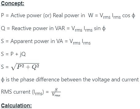
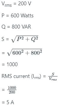
Find the current in the circuit which supplies an active power of 600 watts and reactive power of 800 VAR, if the voltage applied is 200 V (RMS value).
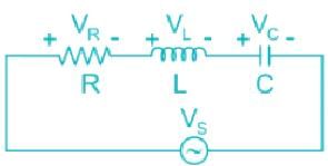

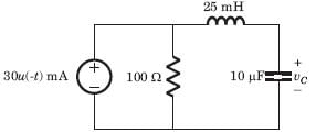
In the circuit of fig. v∞ = 0 for t > 0. The initial condition are v(0) = 6V and dv(0) /dt =-3000 V s. The v(t) for t > 0 is
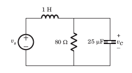
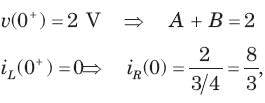
The circuit shown in fig. P1.6.5 has been open for a long time before closing at t = 0. The initial condition is v(0) = 2V. The v(t) for t > is
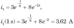
Circuit is shown in fig. Initial conditions are i1(0) = i2(0) =11A
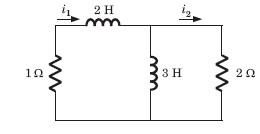
i1 (1s) = ?
Circuit is shown in fig. P.1.6. Initial conditions are (0)i1=i2(0)=11A
i2 (1 s)= ?
The circuit shown in fig is in steady state with switch open. At t = 0 the switch is closed. Theoutput voltage vt (c) for t > 0 is
The switch of the circuit shown in fig. is opened at t = 0 after long time. The v(t) , for t > 0 is
In the circuit of fig.the switch is opened at t = 0 after long time. The current iL(t) for t > 0 is
In the circuit shown in fig.all initial condition are zero.
If is (t) = 1 A, then the inductor current iL(t) is
In the circuit shown in fig. all initialcondition are zero
If is(t) = 0.5t A, then iL(t) is
In the circuit of fig. switch is moved from position a to b at t = 0. The iL(t) for t > 0 is
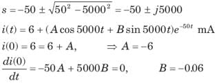
In the circuit shown in fig. a steady state has been established before switch closed. The i(t) for t > 0 is
The switch is closed after long time in the circuit of fig. The v(t) for t > 0 is
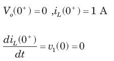
In the circuit of fig. i(0) = 1A and v(0) = 0. The current i(t) for t > 0 is
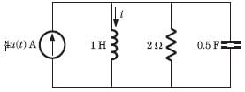
In the circuit of fig. a steady state has been established before switch closed. The vo (t) for t >0 is
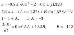
In the circuit of fig. a steady state has been established before switch closed. The i(t) for t > 0 is
Calculate the quality factor Q for an RLC circuit having R = 10 Ω, C = 30μF, and L = 27mH.


