Test: Power Systems- 4 - Electrical Engineering (EE) MCQ
10 Questions MCQ Test - Test: Power Systems- 4

Consider the following statements:
The VAR injection in a power system is obtained by:
1. Tap changing transformers
2. Synchronous condensers
3. Capacitor and inductor banks
4. Inductor banks
Which of the following statements given above are correct?
An induction motor operating at 0.8 pf lag consuming 500 kW. A zero real power consuming synchronous motors is connected across the induction motor raise the power factor to unity. The reactive power drawn by synchronous motor is___ (kVAR)
| 1 Crore+ students have signed up on EduRev. Have you? Download the App |
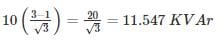
A 10 kW induction motor initially operating on a power factor of 0.5 lagging. If power factor is improved to 0.866 lagging than what is the value of kVAr raised
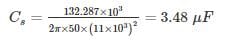
Shunt capacitor are used to raise the power factor of the load of 150 kW from 0.75 lag to unity, the supply being 3 – phase at 11 kV. In star bank the capacitance will be – (in μF)
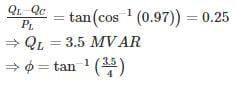
At an Industrial substation with a 4 MW load a capacitor of 2.5 MVAR is installed to maintain the load power factor at 0.97 lag. If the capacitor goes out of service, the load power factor becomes –
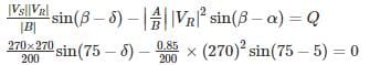
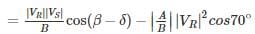
A 270 KV transmission line has the following line constants A = 0.85∠5° ; B = 200∠75°. What is the power that can be received if the voltage profile at each end is maintained at 270 KV (in MW) –
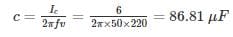
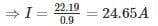
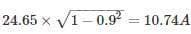
A single phase 50 Hz motor takes 20 A at 0.75 power factor lagging from a 220 V sinusoidal supply. The capacitance required to be connected in parallel to raise the power factor to 0.9 lagging is ______ (in μF)
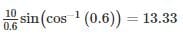
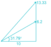
A single – phase inductive load is drawing 10 MW at 0.6 power factor lagging. A capacitor is added in parallel across the load to improve the power factor to 0.85. What is the reactive power required for the capacitor?
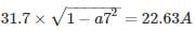
A single phase motor connected to 400V, 50Hz supply takes 31.7 A at a power factor of 0.7 lagging. Calculate the capacitance (in μF) required in parallel with the motor to raise the power factor to 0.9 lagging.
A supply system feeds the following loads
(i) A lighting load of 500 kW
(ii) A load of 400 kW at a p.f. 0.707 lagging
(iii) A load of 800 kW at a p.f. 0.8 leading
(iv) A load of 500 kW at a p.f. 0.6 lagging
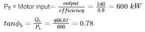
(v) A synchronous motor driving a 540 kW d.c. generator and having an overall efficiency of 90%
Calculate the power factor of the synchronous motor so that station power factor may become unity.
Top Courses for Electrical Engineering (EE)


Important Questions for Power Systems- 4
Power Systems- 4 MCQs with Answers
Online Tests for Power Systems- 4
|
© EduRev
|
Education Revolution
|


Follow Us
|


within 7 days!