Test: Power Systems- 5 - Electrical Engineering (EE) MCQ
10 Questions MCQ Test - Test: Power Systems- 5

A power system has 200 busses including 15 generator buses. For the load flow analysis using the Newton-Raphson method in polar coordinates, the size of the Jacobian is
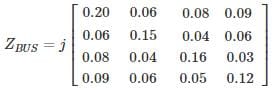
The Zbus of a system is
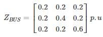
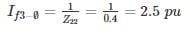
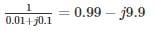
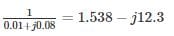
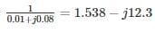
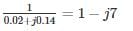
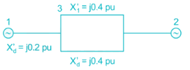
If a 3 phase fault occurs at BUS – 2, the p.u. fault current in each phase is – (in pu)
If a 3 phase fault occurs at BUS – 2, the p.u. fault current in each phase is – (in pu)
| 1 Crore+ students have signed up on EduRev. Have you? Download the App |
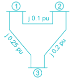
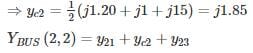
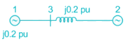
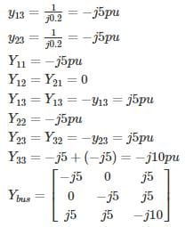
A single line diagram of a power system is shown in the figure. The per unit values of line impedances are given. The sum of diagonal elements of YBUS matrix is
The power system network is having a 60 bus system. The YbusYbus of this power system network is having 70% of sparse. The minimum number of transmission lines that exist in the bus system___
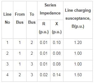
The single line diagram of a power system network having 3 buses and 4 lines is shown in the figure below. The line data is provided in the associated table. The values of the (2, 2) and (2,1) elements of the bus admittance matrix (YBUS) are
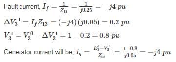
For a Z bus system Z11 = j0.25,Z12 = j0.02,Z13 = j0.05,z14 = j0.04
There are 2 generators at bus 1 and 3 and their sub-transient reactance was induced while calculating Z bus. A three-phase fault occurs at bus 1. The magnitude of pu current supplied by generator 3 whose sub-transient reactance is j0.05 pu is___ (in pu)
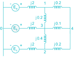
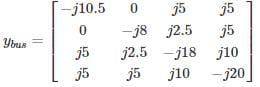
The bus admittance matrix for the network shown in the figure is
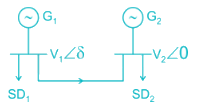
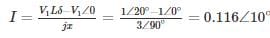
Two generators G1 and G2 are connected with cable having a reactance of j3 PU and the load demand at two buses are SD1 = 20 + j20 PU and SD2 = 25 + j2.5 PU the total reactive power in PU at the generating station G1 when δ = 20° is ______ PU
A generator is connected to an infinite bus through a double circuit line as shown
The admittance matrix Y is given by
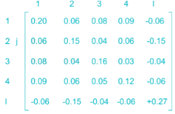
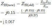
The bus impedance matrix of a 4 – bus power system network is given by
An element having an impedance of j 0.12 pu is connected b/n ref bus and bus 2. Calculate new value of Z22.
Top Courses for Electrical Engineering (EE)
Important Questions for Power Systems- 5
Power Systems- 5 MCQs with Answers
Online Tests for Power Systems- 5
|
© EduRev
|
Education Revolution
|


Follow Us
|