Electronics and Communication Engineering (ECE) Exam  >  Electronics and Communication Engineering (ECE) Tests  >  GATE ECE (Electronics) Mock Test Series 2025  >  Test: The RLC Circuits - Electronics and Communication Engineering (ECE) MCQ

Test: The RLC Circuits - Electronics and Communication Engineering (ECE) MCQ


Test Description

20 Questions MCQ Test GATE ECE (Electronics) Mock Test Series 2025 - Test: The RLC Circuits

Test: The RLC Circuits for Electronics and Communication Engineering (ECE) 2025 is part of GATE ECE (Electronics) Mock Test Series 2025 preparation. The Test: The RLC Circuits questions and answers have been prepared according to the Electronics and Communication Engineering (ECE) exam syllabus.The Test: The RLC Circuits MCQs are made for Electronics and Communication Engineering (ECE) 2025 Exam. Find important definitions, questions, notes, meanings, examples, exercises, MCQs and online tests for Test: The RLC Circuits below.
Solutions of Test: The RLC Circuits questions in English are available as part of our GATE ECE (Electronics) Mock Test Series 2025 for Electronics and Communication Engineering (ECE) & Test: The RLC Circuits solutions in Hindi for GATE ECE (Electronics) Mock Test Series 2025 course. Download more important topics, notes, lectures and mock test series for Electronics and Communication Engineering (ECE) Exam by signing up for free. Attempt Test: The RLC Circuits | 20 questions in 60 minutes | Mock test for Electronics and Communication Engineering (ECE) preparation | Free important questions MCQ to study GATE ECE (Electronics) Mock Test Series 2025 for Electronics and Communication Engineering (ECE) Exam | Download free PDF with solutions
Test: The RLC Circuits - Question 1

The natural response of an RLC circuit is described by the differential equation

The v(t) is

Detailed Solution for Test: The RLC Circuits - Question 1

S2 + 2s + 1 = 0 ⇒ s = -1, -1,
v(t) = (A1 + A2t)e-t
v(0) = 10V, 
A1 = A2 = 10

Test: The RLC Circuits - Question 2

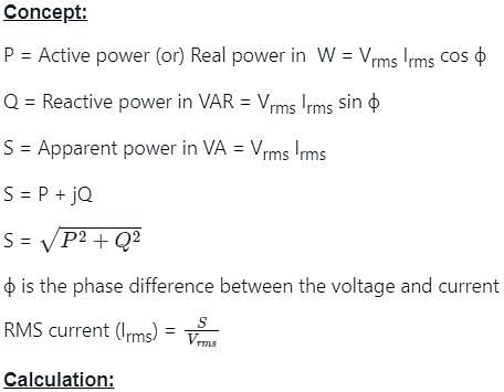
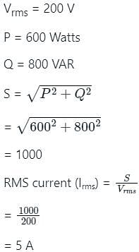
Find the current in the circuit which supplies an active power of 600 watts and reactive power of 800 VAR, if the voltage applied is 200 V (RMS value).
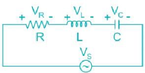
Detailed Solution for Test: The RLC Circuits - Question 2

Test: The RLC Circuits - Question 3

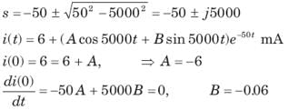
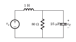
In the circuit of fig. v = 0 for t > 0. The initial condition are v(0) = 6V and dv(0) /dt =-3000 V s. The v(t) for t > 0 is
Detailed Solution for Test: The RLC Circuits - Question 3


⇒ 

⇒ 


Test: The RLC Circuits - Question 4

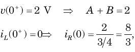
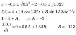
The circuit shown in fig. P1.6.5 has been open for a long time before closing at t = 0. The initial condition is v(0) = 2V. The v(t) for t > is

Detailed Solution for Test: The RLC Circuits - Question 4

The characteristic equation is
After putting the values, 
v(t) = Ae -t + Be-3t


Test: The RLC Circuits - Question 5

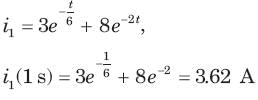
Circuit is shown in fig. Initial conditions are i1(0) = i2(0) =11A
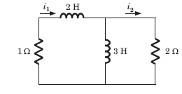
i1 (1s) = ?

Detailed Solution for Test: The RLC Circuits - Question 5


In differential equation putting t = 0 and sovling

Test: The RLC Circuits - Question 6

Circuit is shown in fig. P.1.6. Initial conditions are (0)i1=i2(0)=11A

i2 (1 s)= ?

Detailed Solution for Test: The RLC Circuits - Question 6


C = -1 and D = 12

Test: The RLC Circuits - Question 7

v(t ) =? for t > 0

Detailed Solution for Test: The RLC Circuits - Question 7


Test: The RLC Circuits - Question 8

The circuit shown in fig is in steady state with switch open. At t = 0 the switch is closed. Theoutput voltage vt (c) for t > 0 is

Detailed Solution for Test: The RLC Circuits - Question 8


Test: The RLC Circuits - Question 9

The switch of the circuit shown in fig. is opened at t = 0 after long time. The v(t) , for t > 0 is

Detailed Solution for Test: The RLC Circuits - Question 9


A2 = -4

Test: The RLC Circuits - Question 10

In the circuit of fig.the switch is opened at t = 0 after long time. The current iL(t) for t > 0 is

Detailed Solution for Test: The RLC Circuits - Question 10


Test: The RLC Circuits - Question 11

In the circuit shown in fig.all initial condition are zero.

If is (t) = 1 A, then the inductor current iL(t) is 

Detailed Solution for Test: The RLC Circuits - Question 11


Test: The RLC Circuits - Question 12

In the circuit shown in fig. all initialcondition are zero

If is(t) = 0.5t A, then iL(t) is

Detailed Solution for Test: The RLC Circuits - Question 12

Trying iL (t)= At+ B,


Test: The RLC Circuits - Question 13

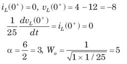
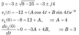
In the circuit of fig. switch is moved from position a to b at t =  0. The iL(t) for t > 0 is

Detailed Solution for Test: The RLC Circuits - Question 13


α = ωo critically damped
v(t) = 12 + (A + Bt)e-5t
0 = 12 + A, 150 = -5A + B A = -12, B = 90
v(t) =12 + (90t -12)e-5t 
iL(t) = 0.02(-5) e-5t(90t -12) +0.02(90)e-5t = (3 -9t)e-5t

Test: The RLC Circuits - Question 14

In the circuit shown in fig. a steady state has been established before switch closed. The i(t) for t > 0 is

Detailed Solution for Test: The RLC Circuits - Question 14

Test: The RLC Circuits - Question 15

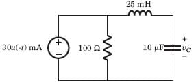
The switch is closed after long time in the circuit of fig. The v(t) for t > 0 is

Detailed Solution for Test: The RLC Circuits - Question 15


Test: The RLC Circuits - Question 16

i(t) = ?

Detailed Solution for Test: The RLC Circuits - Question 16

Test: The RLC Circuits - Question 17

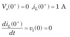
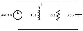
In the circuit of fig. i(0) = 1A and v(0) = 0. The current i(t) for t > 0 is
Detailed Solution for Test: The RLC Circuits - Question 17


Test: The RLC Circuits - Question 18

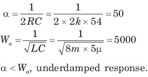
In the circuit of fig. a steady state has been established before switch closed. The vo  (t) for t >0 is

Detailed Solution for Test: The RLC Circuits - Question 18

α = Wo, So critically damped respones
s = -10, -10

Test: The RLC Circuits - Question 19

In the circuit of fig. a steady state has been established before switch closed. The i(t) for t > 0 is

Detailed Solution for Test: The RLC Circuits - Question 19


α = Wo, critically damped response

s = -2, -2
i(t) = (A + Bt)e-2t, A = -2

At t = 0. ⇒ B = -2

Test: The RLC Circuits - Question 20

Calculate the quality factor Q for an RLC circuit having R = 10 Ω, C = 30μF, and L = 27mH.

Detailed Solution for Test: The RLC Circuits - Question 20

CONCEPT:

RLC CIRCUIT:


  •  An RLC circuit is an electrical circuit consisting of an inductor (L), Capacitor (C), Resistor (R) it can be connected either parallel or series.
  • When the LCR circuit is set to resonate (XL = XC), the resonant frequency is expressed as 

⇒f=12π1LC

  • Quality factor is

 ⇒Q=ω0LR=1RLC

Where, XL & XC = Impedance of inductor and capacitor, L, R & C = Inductance, resistance, and capacitance, f = frequency and, ω0 = angular resonance frequency

CALCULATION:

Given that: R = 10 Ω, C = 30 μF = 30 × 10-6 F, and L = 27mH = 27 × 10-3 H

From the above discussion,

⇒Q=ω0LR=1RLC

⇒Q=11027×10−330××10−6

⇒Q=3×1010=3

  • Hence option (1) is correct.
25 docs|263 tests
Information about Test: The RLC Circuits Page
In this test you can find the Exam questions for Test: The RLC Circuits solved & explained in the simplest way possible. Besides giving Questions and answers for Test: The RLC Circuits, EduRev gives you an ample number of Online tests for practice
Download as PDF