Analog Electronics - 6 - Free MCQ Test with solutions for GATE EE and Digital
MCQ Practice Test & Solutions: Analog Electronics - 6 (10 Questions)
You can prepare effectively for Electrical Engineering (EE) Analog and Digital Electronics with this dedicated MCQ Practice Test (available with solutions) on the important topic of "Analog Electronics - 6". These 10 questions have been designed by the experts with the latest curriculum of Electrical Engineering (EE) 2026, to help you master the concept.
Test Highlights:
- - Format: Multiple Choice Questions (MCQ)
- - Duration: 30 minutes
- - Number of Questions: 10
Sign up on EduRev for free to attempt this test and track your preparation progress.

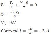
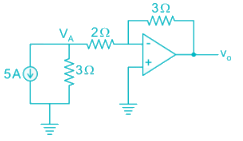
The current flowing through the 3 Ω resistor R1 is _____ A.
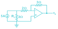
Detailed Solution: Question 1

An op-amp has a voltage gain of 100 dB at dc and a unity gain frequency of 5 MHz. The lower 3-dB cut off frequency is _______ Hz.
Detailed Solution: Question 2


An op-amp with slew rate 1 V/μ is used in the circuit below input step voltage Vi = V sin (105t) is given, the maximum value of V such that no raise time distortion occurs at the output is _____V.
Detailed Solution: Question 3

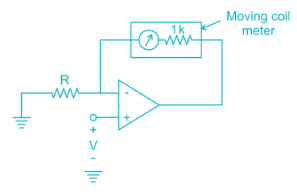
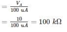
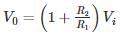
The circuit shows an analog voltmeter of very high input impedance that uses an inexpensive moving coil-meter. The voltmeter measures the voltage ‘V’ applied between the op-amp’s positive-input terminal and ground. Assuming that the moving coil produces full-scale deflection when the current passing through it is 100 μA, the value of R (in kΩ) to obtain full-scale reading at +10 V is
Detailed Solution: Question 4
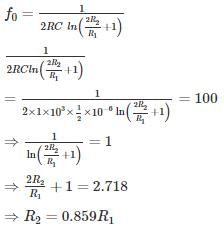
Circuit shows an op-amp circuit used for generating the square waveform.
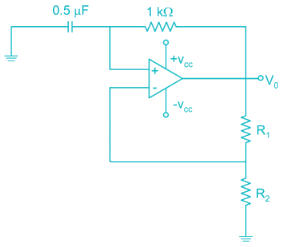
If the output frequency required in 1 kHz. then the possible values of R1 and R2 can be respectively
If the output frequency required in 1 kHz. then the possible values of R1 and R2 can be respectively
Detailed Solution: Question 5
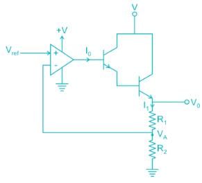
The circuit shows the series voltage regulator.
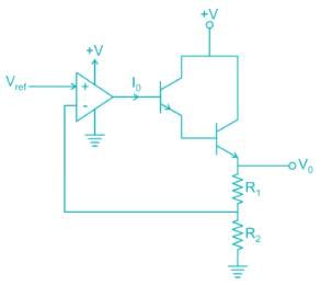
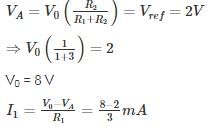
If reference voltage Vref is 2V and R1 = 3K, R2 = 1K, β = 99 for both transistors. Then the value of current I0 in micro-amperes is _____ μA.
If reference voltage Vref is 2V and R1 = 3K, R2 = 1K, β = 99 for both transistors. Then the value of current I0 in micro-amperes is _____ μA.
Detailed Solution: Question 6

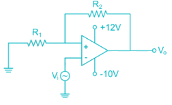
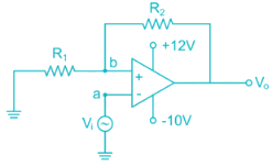
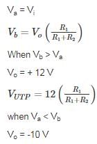
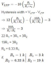
The circuit shows an – op-amp in Schmidt Trigger configuration. If the hysteresis width is 3V. Then the value of R1 and R2 is
Detailed Solution: Question 7
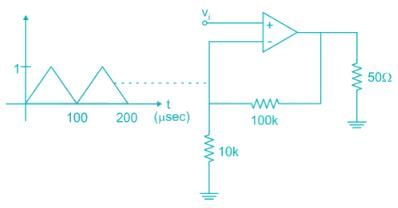
For the amplifier circuit shown, the op-amp can deliver a maximum current of 100 mA and is powered by ±15 V supply. If the input to the amplifier is a triangular waveform as shown. The peak value of the output waveform is ______.
Detailed Solution: Question 8
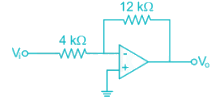
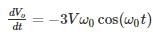
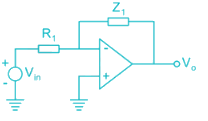
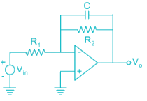
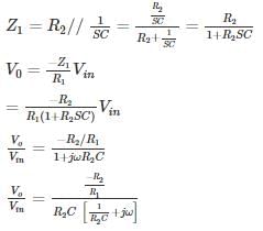
An op-amp circuit is shown in the figure. If Vin is an AC source of frequency ω.
Consider the following statements:
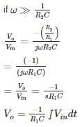
a) For ω  Circuit is an integrator
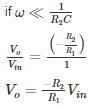
(b) For ω  circuit is an Amplifier
Consider the following statements:
a) For ω
Circuit is an integrator(b) For ω
circuit is an AmplifierDetailed Solution: Question 9
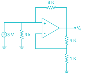
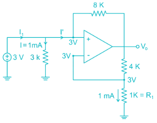
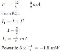
The average power delivered by the 3 V source is ________ mW.
Detailed Solution: Question 10

135 videos|183 docs|71 tests |