Test: Circuit Outputs - Computer Science Engineering (CSE) MCQ
30 Questions MCQ Test - Test: Circuit Outputs

The time required for a pulse to decrease from 90 to 10 per cent of its maximum value is called

Multiple choices can be correct. Mark all of them.
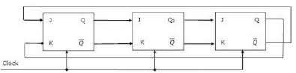
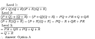
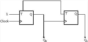
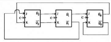
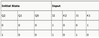
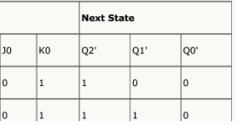
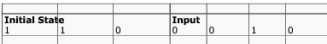
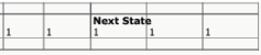
For the initial state of 000, the function performed by the arrangement of the J-K flip-flops in figure is:
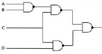
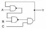
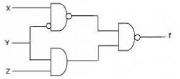
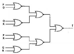
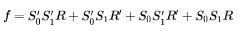
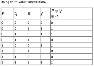
The logic expression for the output of the circuit shown in figure below is:
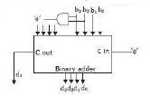
Consider the circuit in Fig.2.21 which has a four bit binary number  as input and a five bit binary number,
  as output.
Consider a logic circuit shown in figure below. The functions (in canonical sum of products form in decimal notation) are :
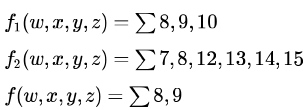
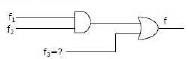
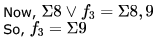
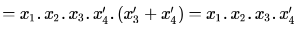
The function

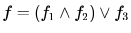
 are in canonical sum of products form,
 will only contain their common terms- that is
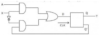
Consider the circuit shown below. In a certain steady state, the line  . What are the possible values of and in this state?
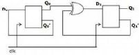
The following arrangement of master-slave flip flops
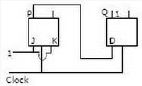
has the initial state of P, Q as 0, 1 (respectively). After a clock cycle the output state P, Q is (respectively),
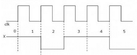
Consider the following circuit with initial state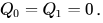 The D Flip-flops are positive edged triggered and have set up times 20 nanosecond and hold times 0.
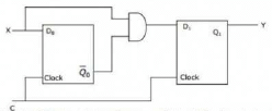
Consider the following timing diagrams of X and C. The clock period of  nanosecond. Which one is the correct plot of Y?
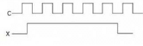
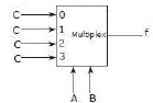
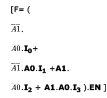
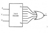
Consider the following multiplexer where 10, 11, 12, 13 are four data input lines selected by two address line combinations A1A0=00,01,10,11 respectively and f is the output of the multiplexor. EN is the Enable input.
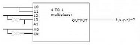
The function f(x,y,z) implemented by the above circuit is
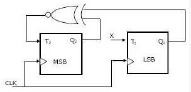
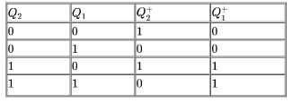
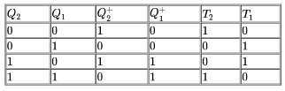
Consider the partial implementation of a 2-bit counter using T flip-flops following the sequence 0-2-3-1-0, as shown below.

Consider the following circuit.
Which one of the following is TRUE?
Consider the following circuit involving a positive edge triggered D FF.
Consider the following . represents the logic level on the line a in the i-th clock period.
 represent the compliment of A. The correct output sequence on A over the clock periods 1 through is:
Consider the following circuit:
The flip-flops are positive edge triggered D FFs. Each state is designated as a two-bit string Q0Q1. Let the initial state be 00. The state transition sequence is
A two-way switch has three terminals a, b and c. In ON position (logic value 1), a is connected to b, and in OFF position, a is connected to c. Two of these two-way switches S1 and S2 are connected to a bulb as shown below.
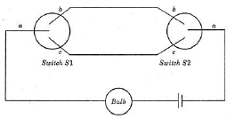
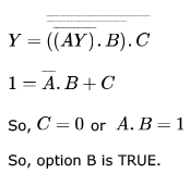
Which of the following expressions, if true, will always result in the lighting of the bulb ?
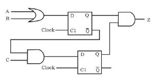
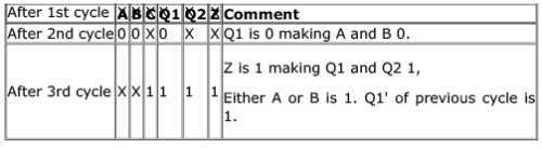
Which of the following input sequences will always generate a 1 at the output z at the end of the third cycle?

Consider the circuit above. Which one of the following options correctly represents 
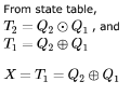
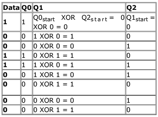
Consider the circuit in the diagram. The operator represents Ex-OR. The D flip-flops are initialized to zeroes (cleared).
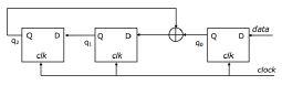
The following data: 100110000 is supplied to the “data” terminal in nine clock cycles. After that the values of q2q1q0 are:
The control signal functions of a 4-bit binary counter are given below (where X is “don’t care”):
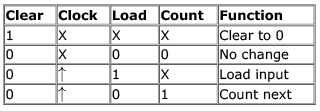
The counter is connected as follows:
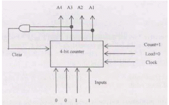
Assume that the counter and gate delays are negligible. If the counter starts at 0, then it cycles through the following sequence:
The following expression was to be realized using 2-input AND and OR gates. However, during the fabrication all 2-input AND gates were mistakenly substituted by 2-input NAND gates. (a.b).c + (a'.c).d + (b.c).d + a. d
What is the function finally realized ?
The line T in the following figure is permanently connected to the ground.
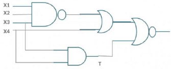
Which of the following inputs (X1 X2 X3 X4) will detect the fault ?
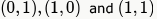 and and output will be 1 for (0,0).
 , the OR gate makes 1 output and we won't get
  input for the final gate. This means, no input sequence can detect the fault of the circuit.
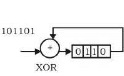
What is the final value stored in the linear feedback shift register if the input is 101101?
What is the boolean expression for the output f of the combinational logic circuit of NOR gates given below?
In the sequential circuit shown below, if the initial value of the output Q1Q0 is 00. What are the next four values of Q1Q0 ?
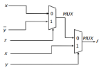
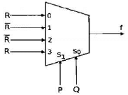
The Boolean expression of the output f of the multiplexer shown below is


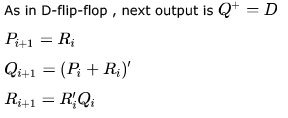
Consider the following circuit involving three D-type flip-flops used in a certain type of counter configuration.
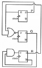
If at some instance prior to the occurrence of the clock edge,
P,Q and R have a value 0, 1 and 0 respectively, what shall be the value of PQR after the clock edge
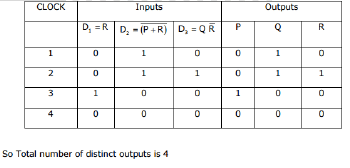
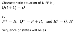
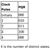
Consider the following circuit involving three D-type flip-flops used in a certain type of counter configuration.
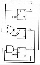
If all the flip-flops were reset to 0 at power on, what is the total number of distinct outputs (states) represented by PQR generated by the counter?
The above synchronous sequential circuit built using JK flip-flops is initialized with 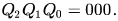 The state sequence for this circuit for the next 3 clock cycles is


Important Questions for Circuit Outputs
Circuit Outputs MCQs with Answers
Online Tests for Circuit Outputs
|
© EduRev
|
Education Revolution
|


|


