Test: Coupled Circuits - 3 - Electrical Engineering (EE) MCQ
10 Questions MCQ Test - Test: Coupled Circuits - 3

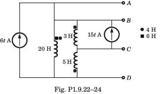
Consider the circuit shown in fig. P1.9.22–24.

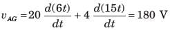
Q. The voltage VAG of terminal AD is
Q. The voltage VAG of terminal AD is
| 1 Crore+ students have signed up on EduRev. Have you? Download the App |
Consider the circuit shown in fig. P1.9.22–24.
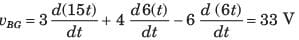
Q. The voltage vBG of terminal BD is
Q. The voltage vBG of terminal BD is
Consider the circuit shown in fig. P1.9.22–24.

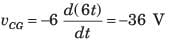
Q. The voltage vCG of terminal CD is
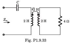
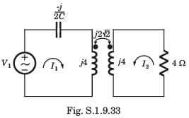
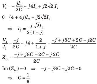
In the circuit of fig. P1.9.33 the ω = 2 rad/s. The resonance occurs when C is
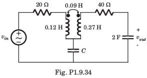
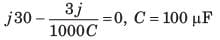
In the circuit of fig. P1.9.34, the voltage gain is zero at ω = 333.33 rad/s. The value of C is
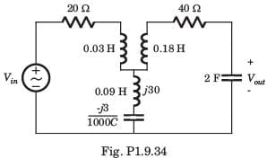
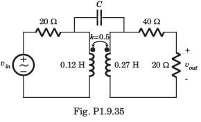
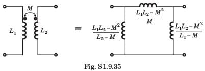
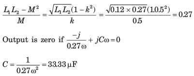
In the circuit of fig. P1.9.35 at ω = 333.33 rad/s, the voltage gain vout/vin is zero. The value of C is
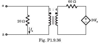
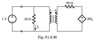
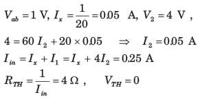
The Thevenin equivalent at terminal ab for the network shown in fig. P1.9.36 is
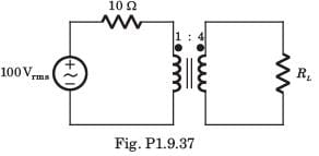
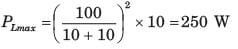
In the circuit of fig. P1.9.37 the maximum power delivered to RL is
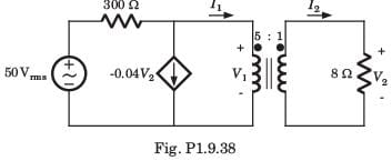
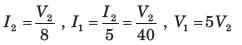
The average power delivered to the 8Ω load in the circuit of fig. P1.9.38 is
Top Courses for Electrical Engineering (EE)


Important Questions for Coupled Circuits - 3
Coupled Circuits - 3 MCQs with Answers
Online Tests for Coupled Circuits - 3
|
© EduRev
|
Education Revolution
|


Follow Us
|