Test: Transient Response of DC & AC Networks - 1 - Electrical Engineering (EE) MCQ
10 Questions MCQ Test Network Theory (Electric Circuits) - Test: Transient Response of DC & AC Networks - 1

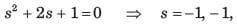
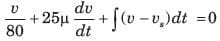
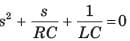
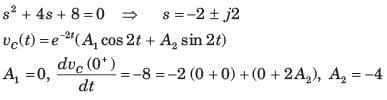
The natural response of an RLC circuit is described by the differential equation
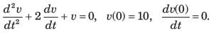
The v(t) is
The v(t) is
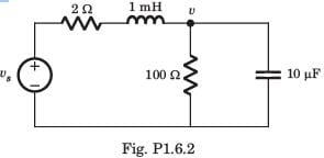
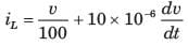
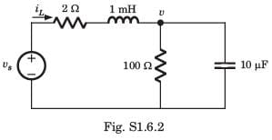
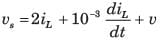
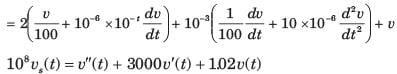
The differential equation for the circuit shown in fig. P1.6.2. is
| 1 Crore+ students have signed up on EduRev. Have you? Download the App |
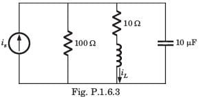
The differential equation for the circuit shown in fig. P1.6.3 is
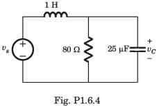
In the circuit of fig. P.1.6.4 vs = 0 for t > 0. The initial condition are v(0) = 6 V and dv(0) dt = -3000 Vs. The v(t) for t > 0 is
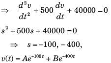
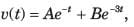
The circuit shown in fig. P1.6.5 has been open for a long time before closing at t = 0. The initial condition is v(0) = 2 V. The v(t) for t > is
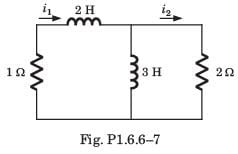
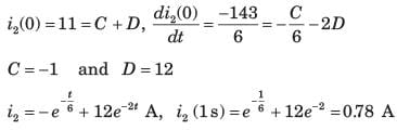
Circuit is shown in fig. P.1.6. Initial conditions are i1(0) = i2(0) = 11A

Q. i1 (1 s) = ?
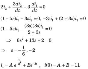
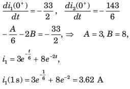
Circuit is shown in fig. P.1.6. Initial conditions are i1(0) = i2(0) = 11A
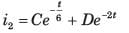
Q. i2 (1 s) = ?
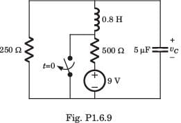
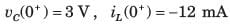
The circuit shown in fig. P1.6.9 is in steady state with switch open. At t = 0 the switch is closed. The output voltage vC(t) for t > 0 is
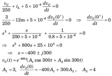
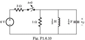
The switch of the circuit shown in fig. P1.6.10 is opened at t = 0 after long time. The v(t) , for t > 0 is
|
68 videos|85 docs|62 tests
|
|
68 videos|85 docs|62 tests
|
Top Courses for Electrical Engineering (EE)


Important Questions for Transient Response of DC & AC Networks - 1
Transient Response of DC & AC Networks - 1 MCQs with Answers
Online Tests for Transient Response of DC & AC Networks - 1 Network Theory (Electric Circuits)
|
© EduRev
|
Education Revolution
|


Follow Us
|