Physics Exam  >  Physics Tests  >  GATE Physics Mock Test Series 2025  >  Test: Electronics - 1 - Physics MCQ

Test: Electronics - 1 - Physics MCQ


Test Description

20 Questions MCQ Test GATE Physics Mock Test Series 2025 - Test: Electronics - 1

Test: Electronics - 1 for Physics 2024 is part of GATE Physics Mock Test Series 2025 preparation. The Test: Electronics - 1 questions and answers have been prepared according to the Physics exam syllabus.The Test: Electronics - 1 MCQs are made for Physics 2024 Exam. Find important definitions, questions, notes, meanings, examples, exercises, MCQs and online tests for Test: Electronics - 1 below.
Solutions of Test: Electronics - 1 questions in English are available as part of our GATE Physics Mock Test Series 2025 for Physics & Test: Electronics - 1 solutions in Hindi for GATE Physics Mock Test Series 2025 course. Download more important topics, notes, lectures and mock test series for Physics Exam by signing up for free. Attempt Test: Electronics - 1 | 20 questions in 40 minutes | Mock test for Physics preparation | Free important questions MCQ to study GATE Physics Mock Test Series 2025 for Physics Exam | Download free PDF with solutions
Test: Electronics - 1 - Question 1

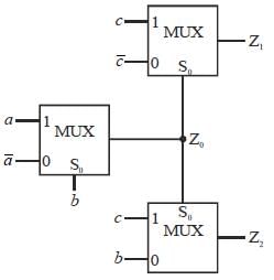
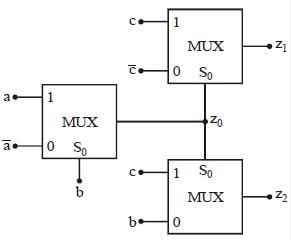
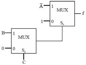
A MUX network is shown below.

The funciton Z1 is

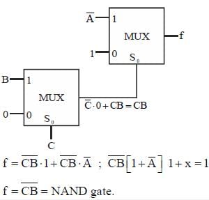
Detailed Solution for Test: Electronics - 1 - Question 1


Test: Electronics - 1 - Question 2

A Silicon PN junction diode under reverse bias lias depletion region of widlit 10 μm. The relative peunittivity of Silicon. εr =11.7 and the permittivity of free space ε0 = 8.85 x 10⁻¹² F/m . The depletion capacitance of the diode per square meter is

Detailed Solution for Test: Electronics - 1 - Question 2

C= depletion capacitance ; 
Depletion capacitance/ m2

1 Crore+ students have signed up on EduRev. Have you? Download the App
Test: Electronics - 1 - Question 3

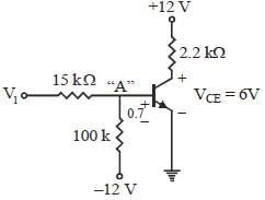
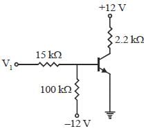
For the transistor shown below. β = 30 and VCEQ = 6 V. The value ofV1 is
Detailed Solution for Test: Electronics - 1 - Question 3

Given β = 30, VCE = 6 V " quiscent point", V1 = ?

We know VBE = 0.7 V, “Si” BJT


K C L at point “A ” 
Put value of IB, V1 = 3.955

Test: Electronics - 1 - Question 4

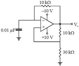
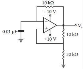
For the square wave generator shown below the frequency is

Detailed Solution for Test: Electronics - 1 - Question 4

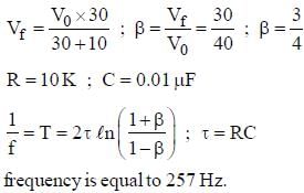
Square wave generator frequency is equal to

Test: Electronics - 1 - Question 5

Detailed Solution for Test: Electronics - 1 - Question 5

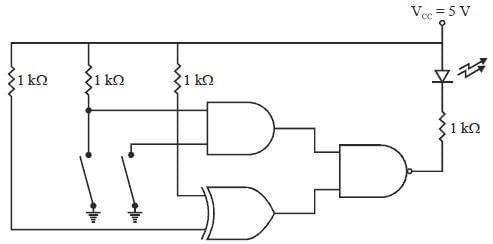
Led will glow when it is in forward bias, it means output of NAND gate is "O’, since p-terminal of led is applied to +5V. Output of NAND gate is always "1” irrespective of the switch position.

Test: Electronics - 1 - Question 6

Detailed Solution for Test: Electronics - 1 - Question 6

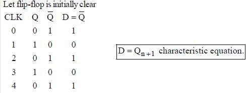
Frequency of output Q = ?


Test: Electronics - 1 - Question 7

The truth table for an S-R flip-flop has how many VALID entries? 

Detailed Solution for Test: Electronics - 1 - Question 7

The SR flip-flop actually has three inputs, Set, Reset and its current state. The Invalid or Undefined State occurs at both S and R being at 1

Test: Electronics - 1 - Question 8

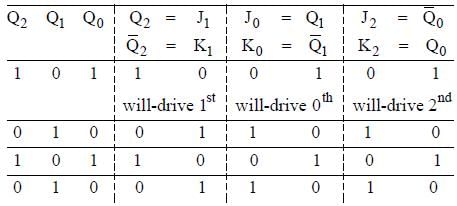
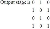
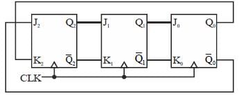
The three-stage Johnson counter as shown in figure below is clocked at a constant frequency of fc from the starting state of Q2Q1Q0 =101. The frequecny of output Q2Q1Q0 will be
Detailed Solution for Test: Electronics - 1 - Question 8

3-stage Johnson-counter ⇒ but not D-flip flop, so find complete output Q2 Q1 Q0 = 1 0 1


Test: Electronics - 1 - Question 9

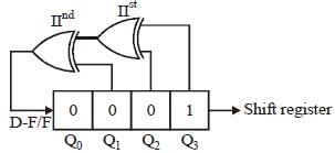
A 4-bit light shift register is initialized to value 1000 for (Q3, Q2, Q1, Q0 ). The D input is derived from Q0, Q2 and Q3 through two XOR gates as shown in figure. The pattern 1000 will appear at

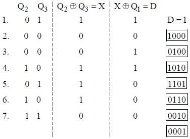
Detailed Solution for Test: Electronics - 1 - Question 9


Hence after clock pulse. Sequence

Q Q2 Q1 Q= 1000 is repeated.
 

Test: Electronics - 1 - Question 10

The network shown below implements

Detailed Solution for Test: Electronics - 1 - Question 10

Frequency is equal to

Test: Electronics - 1 - Question 11

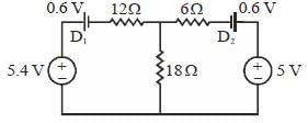
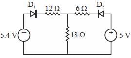
In the circuit shown beolw diodes has cutin voltage of 0.6 V. The dioide in ON state are
Detailed Solution for Test: Electronics - 1 - Question 11


...(a)
.....(b)
Find I1 and I2. if I1 and I2 are positive finite then both the diode are ON. Check: D2-diode-ON

Test: Electronics - 1 - Question 12

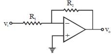
The following circuit is an example of

Detailed Solution for Test: Electronics - 1 - Question 12


Inverting-Amplifier is an example of voltage shunt feedback

Test: Electronics - 1 - Question 13

For the circuit shown below the input voltage vi is as shown in figure.

Assume the RC time constant large and cutin voltage of diode Vγ = 0. The output voltage vo is

Detailed Solution for Test: Electronics - 1 - Question 13


Test: Electronics - 1 - Question 14

The value of C required for sinusoidal oscillation of frequency 1 kHz in the following circuit is

Detailed Solution for Test: Electronics - 1 - Question 14

CKT is standard wein bridge osicllator

Test: Electronics - 1 - Question 15

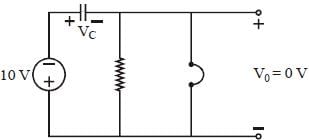
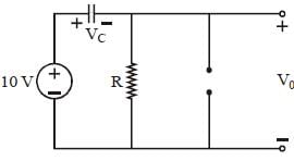
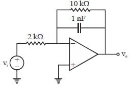
Consider an op-amp circuit shown in figure, input to the circuit is shown in figure, Initially voltage across capacitor is zero,

the output waveform will be

Detailed Solution for Test: Electronics - 1 - Question 15

Given circuit is an LPF-circuit behaves as integrators

Integration of square wave is triangular wave (starting with negative slope)

Test: Electronics - 1 - Question 16

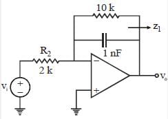
Circuit shown below is a

Detailed Solution for Test: Electronics - 1 - Question 16


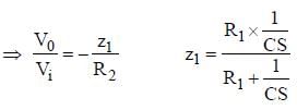
⇒ Low frequency capacitor open,  is finite
⇒ High frequency capacitor short, 
So, its 0 - LPF


Test: Electronics - 1 - Question 17

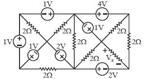
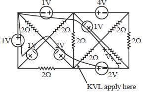
Ill the circuit of figure the voltage Vx is

Detailed Solution for Test: Electronics - 1 - Question 17

Vx = ?

*Answer can only contain numeric values
Test: Electronics - 1 - Question 18

Minimum number of two input NAND gate to design function f = ...........


Detailed Solution for Test: Electronics - 1 - Question 18

Design this function using basic gate first

We Know,

⇒ Add-inverter at output of AND-gate


Therefore. 5 NAND-gate needed.

*Answer can only contain numeric values
Test: Electronics - 1 - Question 19

The full scale output of a 10-bit DAC is 5 V. The resolution is_____________mV


Detailed Solution for Test: Electronics - 1 - Question 19

Test: Electronics - 1 - Question 20

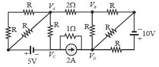
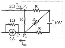
If VA-VB = 6V. then VC - VD is

Detailed Solution for Test: Electronics - 1 - Question 20

Given: VA-VB= 6V and RAB = 2Ω
∴ 
Current enter into the port = Current out from port.
∴ IDC = 3 A

Applying nodal analysis at P.
-2 A - 3A +1 = 0
I = 5A

1 docs|34 tests
Information about Test: Electronics - 1 Page
In this test you can find the Exam questions for Test: Electronics - 1 solved & explained in the simplest way possible. Besides giving Questions and answers for Test: Electronics - 1, EduRev gives you an ample number of Online tests for practice

Up next

Download as PDF

Up next