Test: AC Power Analysis - 1 - Electrical Engineering (EE) MCQ
10 Questions MCQ Test - Test: AC Power Analysis - 1

 for the waveform shown below is
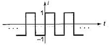
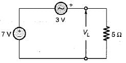
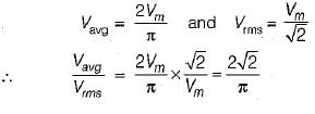
For the idealized full wave rectifier system the average and rms value of the voltage is

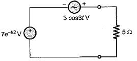
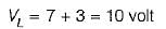
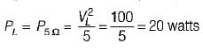
The instantaneous power delivered to the 5 Ω resistor at t = 0 in the given circuit is
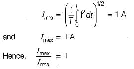
For a sinusoidal waveform, the ratio of average to rms value is
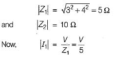
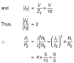
An impedance of (3 + j 4) Ω is connected in parallel with a resistance of 10 Ω. The ratio of power loss in these parallel circuits is
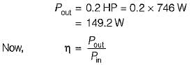
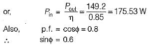
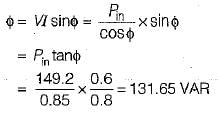
A 0.2 HP induction motor runs at an efficiency of 85%. If the operating power factor is 0.8 lag, the reactive power taken by the motor is
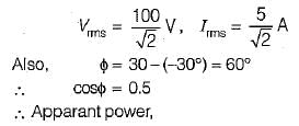
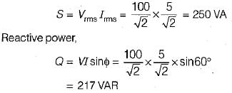
In an a.c. circuit, v = 100 sin (ωt + 30°) V, i = 5 sin(ωt- 30°) A. The apparant and reactive power in the circuit are respectively
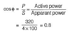
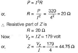
The inductive reactance in series with Z in the circuit shown below has a value of 25 Ω If the voltage drop a cross Z is 179 volts, the power dissipated in the circuit is 320 W.
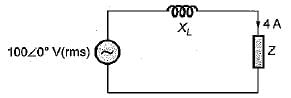
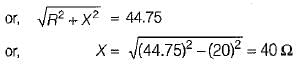
The reactive part of Z is
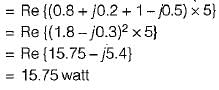
The values of current I1 and I2 in the circuit shown below are given by:
1A = (0.8 + j0.2) A and I2 = -(1 - j0.5) A
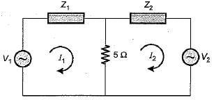
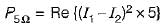
The total power lost in the 5 Ω resistor is


Important Questions for AC Power Analysis - 1
AC Power Analysis - 1 MCQs with Answers
Online Tests for AC Power Analysis - 1
|
© EduRev
|
Education Revolution
|


|


