Electrical Engineering (EE) Exam  >  Electrical Engineering (EE) Tests  >  Power Systems  >  Test: Transmission Line Parameters - Electrical Engineering (EE) MCQ

Test: Transmission Line Parameters - Electrical Engineering (EE) MCQ


Test Description

10 Questions MCQ Test Power Systems - Test: Transmission Line Parameters

Test: Transmission Line Parameters for Electrical Engineering (EE) 2024 is part of Power Systems preparation. The Test: Transmission Line Parameters questions and answers have been prepared according to the Electrical Engineering (EE) exam syllabus.The Test: Transmission Line Parameters MCQs are made for Electrical Engineering (EE) 2024 Exam. Find important definitions, questions, notes, meanings, examples, exercises, MCQs and online tests for Test: Transmission Line Parameters below.
Solutions of Test: Transmission Line Parameters questions in English are available as part of our Power Systems for Electrical Engineering (EE) & Test: Transmission Line Parameters solutions in Hindi for Power Systems course. Download more important topics, notes, lectures and mock test series for Electrical Engineering (EE) Exam by signing up for free. Attempt Test: Transmission Line Parameters | 10 questions in 30 minutes | Mock test for Electrical Engineering (EE) preparation | Free important questions MCQ to study Power Systems for Electrical Engineering (EE) Exam | Download free PDF with solutions
Test: Transmission Line Parameters - Question 1

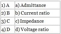
Match the following for ABCD parameters.

Detailed Solution for Test: Transmission Line Parameters - Question 1

Concept:
The ABCD parameters are given by:
V1 = AV2 - BI2
I1 = CV2 - DI2
where, V1 and I1 are the input voltage and current
V2 and I2 are the output voltage and current
Case 1: When output current (I2) = 0
A = V1/V2 = Voltage ratio
C = I1/V2 = Admittanc
Case 2: When output voltage (V2) = 0

Hence, option 2 is correct.

Test: Transmission Line Parameters - Question 2


Calculate the equivalent mutual-GMD of the conductor arrangement.
Given: D12 = 2.5 m, D23 = 4.5 m, D31 = 2 m.

Detailed Solution for Test: Transmission Line Parameters - Question 2

Concept:
For a triangle configuration of conductors , the mutual-GMD is given by:
GMD = (D12 × D23 × D31)1/3
Calculation:
Given;  D12 = 2.5 m, D23 = 4.5 m, D31 = 2 m
GMD = (2.5 × 4.5 × 2)1/3
GMD = 2.82 m

1 Crore+ students have signed up on EduRev. Have you? Download the App
Test: Transmission Line Parameters - Question 3

The most important cause of power loss in the transmission line is:

Detailed Solution for Test: Transmission Line Parameters - Question 3

Series Resistance:

  • The primary source of real power losses incurred in a transmission system is due to the resistance of the conductors.
  • Power loss is directly proportional to the square of the RMS current traveling through the line.
Test: Transmission Line Parameters - Question 4

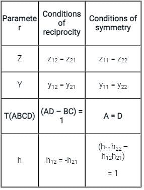
For an ABCD parameter of a transmission line, which of the following is correct?

Detailed Solution for Test: Transmission Line Parameters - Question 4

ABCD Parameter:
We know that the ABCD parameter of the transmission line

A = D
AD – BC = 1
Conditions of reciprocity and symmetry in terms of different two-port parameters are:

Test: Transmission Line Parameters - Question 5

Self GMD method is used to evaluate

Detailed Solution for Test: Transmission Line Parameters - Question 5

Self GMD or GMR:

  • Self GMD is also called GMR. GMR stands for Geometrical Mean Radius. 
  • GMR is calculated for each phase separately.
  • self-GMD of a conductor depends upon the size and shape of the conductor
  • GMR is independent of the spacing between the conductors.

GMD:

  • GMD stands for Geometrical Mean Distance.
  • It is the equivalent distance between conductors.
  • GMD depends only upon the spacing 
  • GMD comes into the picture when there are two or more conductors per phase.​

The inductance of the single-phase two-wire line is

GMD = Mutual Geometric Mean Distance = D
GMR = 0.7788r
r = Radius of the conductor​
The capacitance between two conductors is

In the calculation of the capacitance, the inner radius of the conductor not considered
Therefore, The self GMD method is used to evaluate Inductance only.

*Answer can only contain numeric values
Test: Transmission Line Parameters - Question 6

In the figure shown below, a conductor consists of seven identical strands each having a radius of r.

Determine the factor by which 'r' should be multiplied to find the self GMD of the conductor.


Detailed Solution for Test: Transmission Line Parameters - Question 6


From configuration:
(GMR)1 = (GMR)2 = (GMR)3 = (GMR)5 = (GMR)6 = (GMR)7   

(GMR)4 =(D44 × D41 × D42 × D43 × D45 × D46 × D47)1/7
(GMR)4 = (.7788r × 2r × 2r × 2r × 2r × 2r × 2r)1/7
(GMR)4 = 1.747r 
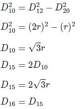
(GMR)1 = (D11 × D12 × D13 × D14 × D17 × D15 × D16)1/7

 (GMR)1 =(.7788r × 2r × 2r × 2r × 4r × 2√3r × 2√3r)1/7
(GMR)1 = 2.257r
GMR=(1.747r × (2.257r)6)1/7
GMR = 2.175r

*Answer can only contain numeric values
Test: Transmission Line Parameters - Question 7

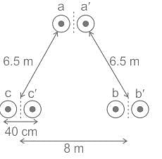
Determine inductance per phase per km in mH of a single circuit 450 kV line using a two-bundle conductor per phase as shown in the figure. (The radius of the conductor is 2.5cm)

Detailed Solution for Test: Transmission Line Parameters - Question 7


= 8.845 cm = 0.08845 m

= 6.96 m
Inductance per phase = 2 × 10-7  
= 8.732 × 10⁻⁷ H/m
= 0.8732 mH/km. 

Test: Transmission Line Parameters - Question 8

The value of inductance per conductor in a three-phase line is _______ time(s) the loop inductance for the single-phase lines.

Detailed Solution for Test: Transmission Line Parameters - Question 8

Loop inductance of a single-phase two-wire line
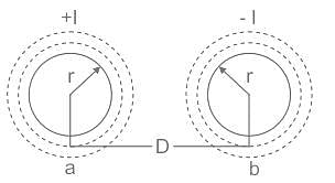
Considered a single-phase line consisting of two conductors (phase and neutral) a and b of equal radius r. They are situated at a distance D meters. The cross sections of conductors are shown in the diagram below.

Let the current flow in the conductors are opposite in direction so that one becomes the return path for the other.
The flux linkages of conductor ‘a’ is given by the formula:

Inductance per conductor in a three-phase line (symmetrical)
Let the spacing between the conductors be D and the radius of each conductor, r. The flux linkages of conductor a is given by the equation:

The flux linkages of the conductor ‘a’ is given by the formula:

Where Daa = r', 
Dab = Dbc =  Dac = D

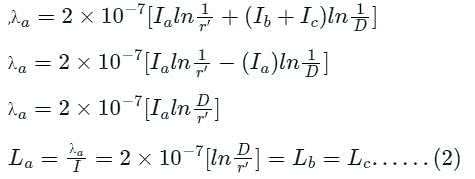
Now from 3 -ϕ,3 wire syste
Ia + Ib + Ic = 0
Ia = - (Ib + Ic)

Where La is the inductance per conductor in a three-phase line 
From equations (1) and (2),
Inductance per conductor in a 3-phase line = (1 / 2) times loop inductance in 1 phase.

Test: Transmission Line Parameters - Question 9

The ABCD constants of a 3 – phase transmission line are-
A = D = 0.8 ∠1°
C = 0.002 ∠90.4° ℧  
B = 170 ∠85° Ω
The sending end voltage is 400 kV. The receiving end voltage under no-load condition is-

Detailed Solution for Test: Transmission Line Parameters - Question 9

ABCD parameters:
ABCD parameters are generalized parameters of the transmission line. Given as
VS = A VR + B IR
IS = C VR + D IR
In matrix form,

VS = Sending end voltage
VR = Receiving end voltage
IS = Sending end current
IR = Receiving end current
A, B, C, D = T-parameter of transmission line
Calculation:
Given:

VS = 400 ∠0° kV 
A = D = 0.8 ∠1°
The system is under no-load condition
So, IR = 0, ⇒ VS = AVR
The receiving end voltage under no-load condition

VR = 500 ∠-1°  kV 

Test: Transmission Line Parameters - Question 10

A single-phase line consists of two long solid conductors, each having a radius of r metre separated by a distance of D metre. What will be capacitance between the conductor?

Detailed Solution for Test: Transmission Line Parameters - Question 10

Concept:
The capacitance between the conductors of a 1-ϕ, 2- long solid conductors transmission line:

D = distance of separation between two long solid conductors
r = radius of each long solid conductor 
qA, q,  = Charge across A and B conductors
The standard result for the capacitance between the conductors
CAB = qA / VAB 
= qB / VBA 
= π ϵr ϵ / ln(D / r)       .....(i 
Calculations:
ϵ = 8.85 × 10⁻¹² 
ϵr  = 1 (for air)
π = 3.14
ln (D / r) = 2.303 log (D / r)
From equation (i)
CAB = (3.14 × 8.85 × 10-12 × 1) / (2.303 log (D / r)) F/m

21 videos|67 docs|45 tests
Information about Test: Transmission Line Parameters Page
In this test you can find the Exam questions for Test: Transmission Line Parameters solved & explained in the simplest way possible. Besides giving Questions and answers for Test: Transmission Line Parameters, EduRev gives you an ample number of Online tests for practice

Top Courses for Electrical Engineering (EE)

21 videos|67 docs|45 tests
Download as PDF

Top Courses for Electrical Engineering (EE)