HC Verma Test: Electrostatic Potential & Capacitance - JEE MCQ
30 Questions MCQ Test Chapter-wise Tests for JEE Main & Advanced - HC Verma Test: Electrostatic Potential & Capacitance
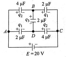
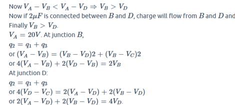
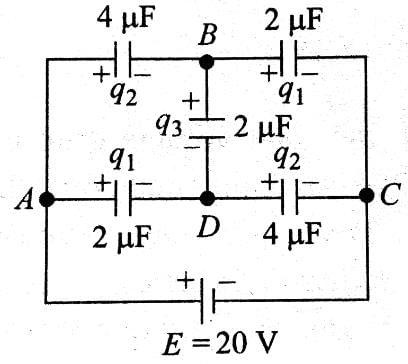
The figure shows a diagonal symmetric arrangement of capacitors and a battery
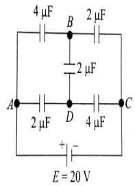
If the potential of C is zero, then

The capacitance of a metallic sphere will be 1mF, if its radius is nearly
Two capacitors of capacitances 1mF and 3mF are charged to the same voltages 5V. They are connected in parallel with oppositely charged plates connected together. Then
Two spherical conductors A and B of radii R and 2R respectively are each given a charge Q. When they are connected by a metallic wire. The charge will
The capacity of a parallel plate condenser is C. Its capacity when the separation between the plates is halved will be
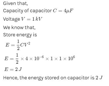
If the p.d. across the ends of a capacitor 4mF is 1.0 kilovolt. Then its electrical potential energy will be
The energy of a charged capacitor resides in
The capacitance of a parallel plate condenser does not depend upon
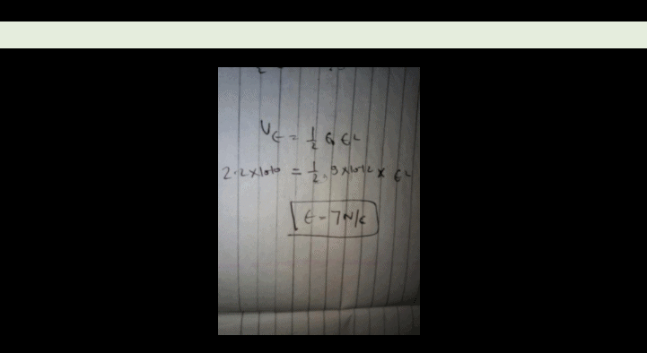
The energy density in a parallel plate capacitor is given as 2.2 × 10⁻¹⁰ J/m3. The value of the electric field in the region between the plates is -
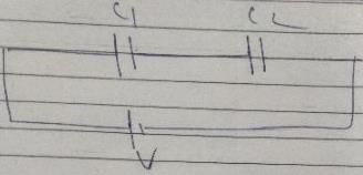
Two capacitances of capacity C1 and C2 are connected in series and potential difference V is applied across it. Then the potential difference acros C1 will be
A conductor of capacitance 0.5mF has been charged to 100volts. It is now connected to uncharged conductor of capacitance 0.2mF. The loss in potential energy is nearly
Two spherical conductors of capacitance 3.0mF and 5.0mF are charged to potentials of 300volt and 500volt. The two are connected resulting in redistribution of charges. Then the final potential is
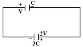
A parallel plate capacitor of capacitance C is connected to a battery and is charged to a potential difference V. Another capacitor of capacitance 2C is similarly charged to a potential difference 2V. The charging battery is now disconnected and the capacitors are connect in parallel to each other in such a way that the positive terminal of one is connected to the negative terminal of the other. The final energy of the configuration is
A 2μF capacitor is charged to a potential = 10 V. Another 4μF capacitor is charged to a potential = 20V. The two capacitors are then connected in a single loop, with the positive plate of one connected with negative plate of the other. What heat is evolved in the circuit?
The figure shows a diagonal symmetric arrangement of capacitors and a battery
Identify the correct statements.

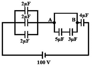
In the circuit shown in figure charge stored in the capacitor of capacity 5μf is
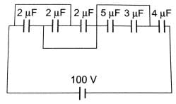
Plate A of a parallel air filled capacitor is connected to a spring having force constant k and plate B is fixed. If a charge +q is placed on plate A and charge _q on plate B then find out extension in spring in equilibrim. Assume area of plate is `A'
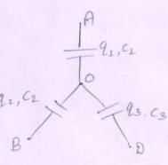
Three uncharged capacitors of capacitane C1 = 1mF, C2 = 2mF and C3 = 3mF are connected as shown in figure to one another and to points A, B and D potential fA = 10V, fB = 25V and fD = 20 V, Determine the potential (f0) at point O.
Five capacitors are connected as shown in the figure. Initially S is opened and all capacitors are uncharged. When S is closed, steady state is obtained. Then find out potential difference between the points M and N.
Find the potential difference Va - Vb between the points a and b shows in each parts of the figure.
Each plate of a parallel plate air capacitor has an area S. What amount of work has to be performed to slowly increase the distance between the plates from x1 to x2 If the charge of the capacitor, which is equal to q or
Each plate of a parallel plate air capacitor has an area S. What amount of work has to be performed to slowly increase the distance between the plates from x1 to x2 If the voltage across the capacitor, which is equal to V, is kept constant in the process.
If charge on left plane of the 5F capacitor in the circuit segment shown in the figure is-20C, the charge on the right plate of 3F capacitor is
In the circuit shown, the energy stored in 1μF capacitor is
A capacitor C1 = 4mF is connected in series with another capacitor C2 = 1mF. The combination is connected across a d.c. source of voltage 200V. The ratio of potential across C1 and C2 is
A 5.0 mF capacitor having a charge of 20 mC is discharged through a wire of resistance of 5.0 W. Find the heat dissipated in the wire between 25 to 50 ms after the capactions are made.
A charged capacitor is allowed to discharge through a resistance 2Ω by closing the switch S at the instant t = 0. At time t = ln2μs, the reading of the ammeter falls half of its initial value. The resistance of the ammeter equal to
A capacitor C =100μF is connected to three resistor each of resistance 1 kW and a battery of emf 9V. The switch S has been closed for long time so as to charge the capacitor. When switch S is opened, the capacitor. Discharges with time constant
In the transient shown the time constant of the circuit is :
In the circuit shown in figure C1 =2C2 . Switch S is closed at time t=0. Let i1 and i2 be the currents flowing through C1 and C2 at any time t, then the ratio i1 / i2
|
481 docs|964 tests
|


