Electrical Engineering (EE) Exam  >  Electrical Engineering (EE) Tests  >  Engineering Services Examination (ESE) Mock Test Series 2024  >  Test: ESE Electrical - 1 - Electrical Engineering (EE) MCQ

Test: ESE Electrical - 1 - Electrical Engineering (EE) MCQ


Test Description

30 Questions MCQ Test Engineering Services Examination (ESE) Mock Test Series 2024 - Test: ESE Electrical - 1

Test: ESE Electrical - 1 for Electrical Engineering (EE) 2025 is part of Engineering Services Examination (ESE) Mock Test Series 2024 preparation. The Test: ESE Electrical - 1 questions and answers have been prepared according to the Electrical Engineering (EE) exam syllabus.The Test: ESE Electrical - 1 MCQs are made for Electrical Engineering (EE) 2025 Exam. Find important definitions, questions, notes, meanings, examples, exercises, MCQs and online tests for Test: ESE Electrical - 1 below.
Solutions of Test: ESE Electrical - 1 questions in English are available as part of our Engineering Services Examination (ESE) Mock Test Series 2024 for Electrical Engineering (EE) & Test: ESE Electrical - 1 solutions in Hindi for Engineering Services Examination (ESE) Mock Test Series 2024 course. Download more important topics, notes, lectures and mock test series for Electrical Engineering (EE) Exam by signing up for free. Attempt Test: ESE Electrical - 1 | 150 questions in 180 minutes | Mock test for Electrical Engineering (EE) preparation | Free important questions MCQ to study Engineering Services Examination (ESE) Mock Test Series 2024 for Electrical Engineering (EE) Exam | Download free PDF with solutions
Test: ESE Electrical - 1 - Question 1

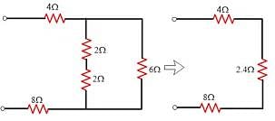
For the circuit given below.

What is the value of equivalent resistance?
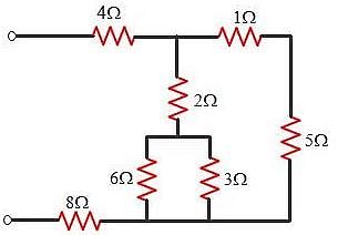
Detailed Solution for Test: ESE Electrical - 1 - Question 1

Test: ESE Electrical - 1 - Question 2

In the circuit given, a charge of 600 C is delivered to the 100 V source in a 1 minute. The value of v1 must be:

Detailed Solution for Test: ESE Electrical - 1 - Question 2
  • In order for 600 C charge to be delivered to the 100 V source, the current must be anticlockwise.
  • Applying KVL we get:
    v1 + 60 - 100 = 10 x 20
    v1 = 240 V
1 Crore+ students have signed up on EduRev. Have you? Download the App
Test: ESE Electrical - 1 - Question 3

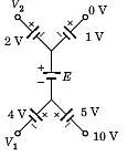
In the circuit of the fig the value of the voltage source E is:
Detailed Solution for Test: ESE Electrical - 1 - Question 3

Going from 10 V to 0 V:

  • 10 + 5 + E + 1 = 0
  • E = -16V
  • Minus sign indicates that the polarity of battery should be reversed.
Test: ESE Electrical - 1 - Question 4

In the case of a sinusoidal current, the unit of the amplitude is:

Detailed Solution for Test: ESE Electrical - 1 - Question 4

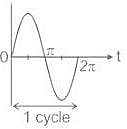
Waveform: The curve obtains by plotting the instantaneous value of any electrical quantity such as voltage, current, or power.

Cycle: One complete set of positive and negative values or maximum or minimum value of the alternating quantity is called a cycle.

Note: One-half cycle of the wave is called Alternation.
Amplitude: the maximum value of the positive or negative alternative quantity is called Amplitude.

  • For sinusoidal current, the unit of the amplitude is amperes.
  • For sinusoidal voltage, the unit of the amplitude is volts.
  • It is also known as peak value or crest value.
  • Peak-Peak Value = 2 × Amplitude
  • In the given figure amplitude of the waveform is Vm.

Time period (T): It is the time required to complete one cycle. It measured in seconds.
Frequency: The number of cycles completed per second is called frequency.
f = 1 / T
It measured in Hz or radian/sec.

Test: ESE Electrical - 1 - Question 5

A sinusoid wave is expressed as 5 sin(4πt – 60°). Find the frequency.

Detailed Solution for Test: ESE Electrical - 1 - Question 5

Concept:
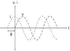
Considered a sinusoidal Alternating wave of voltage and current

From the waveform:
v = Vmsin⁡(ωt)
And,
i = Imsin⁡(ωt + ϕ)
Where Vm and Im are the maximum value of instantaneous voltage and current respectively.
v, i is the instantaneous value of voltage and current at any instant t.
ω is the angular frequency in radian/second.
And, ω = 2πf  
f is the frequency in Hz
From the above three equations instantaneous value of voltage and current can be written as:
v = Vmsin⁡(2πft)
And,
i = Imsin⁡(2πft + ϕ)
Calculation:
Sinusoidal expression of the wave is given as 5 sin (4πt – 60°)
Comparing the above expression with the given equation:
as:
v = Vmsin⁡(2πft)
Or,
i = Imsin⁡(2πft + ϕ)
Hence, ω = 4π
We know that,
ω = 2πf
∴ 4π = 2πf
∴ f = 2 Hz

Test: ESE Electrical - 1 - Question 6

What will be the period of the sinusoid, v(t) = 12 cos (50t + 30°)?

Detailed Solution for Test: ESE Electrical - 1 - Question 6

Concept:
Considered a sinusoidal Alternating wave of voltage and current

From the waveform:
v = Vmsin⁡(ωt)
And,
i = Imsin⁡(ωt + ϕ)
Where Vand Im are the maximum value of instantaneous voltage and current respectively.
v, i is the instantaneous value of voltage and current at any instant t.
ω is the angular frequency in radian/second.
And, ω = 2πf  
f is the frequency in Hz
From the above three equations instantaneous value of voltage and current can be written as:
v = Vmsin⁡(2πft)
And,
i = Imsin⁡(2πft + ϕ)
Calculation:
Sinusoidal wave is given as v = 12 cos (50t + 30°)
Comparing to the given equation
v = Vmsin(ωt ± θ)
ωt = 2πft = 50t
f = 2π50
We know that,

=0.1257sec

Test: ESE Electrical - 1 - Question 7

In a two element series circuit, the applied voltage and the resulting current are v(t) = 60 + 66sin (10 t) V, i(t) = 2.3sin (103t + 68.3o) A.The nature of the elements would be

Detailed Solution for Test: ESE Electrical - 1 - Question 7

R-Ccauses a positive phase shift in voltage

Test: ESE Electrical - 1 - Question 8

[T] = ?

Detailed Solution for Test: ESE Electrical - 1 - Question 8

Let I3 be the clockwise loop current in center loop
 V2 = 4(I2 + I3) ⇒ I3 = 0.25V2 - I2
⇒ I1 = 0.35V2 - I2  .........(i)
V1 = 4I1 - 0.2V1 + V2
1.2V1 = 4(0.35V2 - I2) + V2 = 2.4V2 - 4I2
⇒ V1 = 2V2 - 3.33I2 .........(ii)

Test: ESE Electrical - 1 - Question 9

In a balanced three-phase system-delta load, if we assume the line voltage is VRY = V∠0° as a reference phasor. Then the source voltage VYB is?

Detailed Solution for Test: ESE Electrical - 1 - Question 9

As the line voltage VRY = V∠0° is taken as a reference phasor. Then the source voltage VYB is V∠-120°.

Test: ESE Electrical - 1 - Question 10

If the system is a three-wire system, the currents flowing towards the load in the three lines must add to ___ at any given instant.

Detailed Solution for Test: ESE Electrical - 1 - Question 10

If the system is a three-wire system, the currents flowing towards the load in the three lines must add to zero at any given instant.

Test: ESE Electrical - 1 - Question 11

Find the electric field intensity of transformer oil (εr = 2 approx) with density 1/4π (in 109units) 

Detailed Solution for Test: ESE Electrical - 1 - Question 11

D = εE. E = (1/4π)/(2Xεo) = 4.5 X 10⁹ units.

Test: ESE Electrical - 1 - Question 12

Electric flux density in electric field is referred to as

Detailed Solution for Test: ESE Electrical - 1 - Question 12

Electric flux density is given by the ratio between number of flux lines crossing a surface normal to the lines and the surface area. The direction of D at a point is the direction of the flux lines at that point.

Test: ESE Electrical - 1 - Question 13

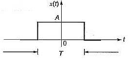
What is the total energy of the rectangular pulse shown in figure below?
Detailed Solution for Test: ESE Electrical - 1 - Question 13

Energy is area under the |x(t)|2 = A2
Area = (A2)*(T)

Test: ESE Electrical - 1 - Question 14

Detailed Solution for Test: ESE Electrical - 1 - Question 14

Test: ESE Electrical - 1 - Question 15

X(z) = ln(1 + z-1), |z| > 0

Detailed Solution for Test: ESE Electrical - 1 - Question 15

Test: ESE Electrical - 1 - Question 16

Given the transform pair below. Determine the time signal y(t) and choose correct option.

Y(s) = (s + 1)X(s)

Detailed Solution for Test: ESE Electrical - 1 - Question 16

Test: ESE Electrical - 1 - Question 17

Given the transform pair below. Determine the time signal y(t) and choose correct option.

Y(s) = X(s + 2)

Detailed Solution for Test: ESE Electrical - 1 - Question 17

Test: ESE Electrical - 1 - Question 18

Consider a periodic signal x[n] with period N and FS coefficients X [k]. Determine the FS coefficients Y [k] of the signal y[n] given in question.

 y[n] = x[n - no]

Detailed Solution for Test: ESE Electrical - 1 - Question 18

Test: ESE Electrical - 1 - Question 19

Consider a periodic signal x[n] with period N and FS coefficients X [k]. Determine the FS coefficients Y [k] of the signal y[n] given in question.

y[n] =  x[n] + x[n + N/2] , (assume that N is even)

Detailed Solution for Test: ESE Electrical - 1 - Question 19

Note that y[n] =  x[n] + x[n + N/2] has a period of N/2 and N has been assumed to be even,

Test: ESE Electrical - 1 - Question 20

Determine the Fourier series coefficient for given periodic signal x(t).

x(t) as shown in fig.

​ ​ ​

Detailed Solution for Test: ESE Electrical - 1 - Question 20

Test: ESE Electrical - 1 - Question 21

The highest frequency component of a speech signal needed for telephonic communications is about 3.1 kHz. What is the suitable value for the sampling rate?

Detailed Solution for Test: ESE Electrical - 1 - Question 21

Nyquist Sampling Theorem: 
A continuous-time signal can be represented in its samples and can be recovered back when sampling frequency fs is greater than or equal to twice the highest frequency component of the message signal, i.e.
fs ≥ 2fm
Therefore when we want to convert continuous signals to discrete signals, the sampling must be done at the Nyquist rate.
Calculation:
Given that,
fm = 3.1 kHz 
⇒ fs ≥ 2fm
⇒ fs ≥ 2 × 3.1 = 6.4 kHz

Test: ESE Electrical - 1 - Question 22

 If X(k) is the DFT of x(n) which is defined as x(n)=x1(n)+jx2(n), 0≤ n≤ N-1, then what is the DFT of x1(n)?

Detailed Solution for Test: ESE Electrical - 1 - Question 22

We know that if x(n)=x1(n)+jx2(n) then x1(n)= (x(n)+x*(n))/2
On applying DFT on both sides of the above equation, we get
X1(k)= 1/2 {DFT[x(n)]+DFT[x*(n)]}
We know that if X(k) is the DFT of x(n), the DFT[x*(n)]=X*(N-k)
⇒X1(k)= 1/2 [X*(k)+X*(N-k)].

Test: ESE Electrical - 1 - Question 23

Which of the following condition should the unit sample response of a FIR filter satisfy to have a linear phase?

Detailed Solution for Test: ESE Electrical - 1 - Question 23

An FIR filter has an linear phase if its unit sample response satisfies the condition
h(n)= ±h(M-1-n) n=0,1,2…M-1.

Test: ESE Electrical - 1 - Question 24

The roots of the equation H(z) must occur in:

Detailed Solution for Test: ESE Electrical - 1 - Question 24

We know that the roots of the polynomial H(z) are identical to the roots of the polynomial H(z -1). Consequently, the roots of H(z) must occur in reciprocal pairs.

Test: ESE Electrical - 1 - Question 25

Consider the following statements regarding control systems:

  1. In open loop control system, the control action depends upon the desired output.
  2. All control systems operated by present timing mechanism are open loop.
  3. In a closed loop control system feedback signal is usually negative.
  4. In open-loop control system stability cannot be ensured.

Which of the above statements are correct?

Detailed Solution for Test: ESE Electrical - 1 - Question 25
  • There is no-control action in open loop systems. Hence, statement 1 is false.
  • Generally, all control systems operated by present timing mechanism are open loop because they are more stable than closed loop control system. Hence, statement-2 is true.
  • Due to various advantages of negative feedback systems (except reduction in gain), feedback signal is usually negative in a closed loop control system. Hence, statement-3 is true.
  • In open-loop control systems stability can be ensured because they are more stable than closed-loop control system.
  • Thus, only statements 2 and 3 are true.
Test: ESE Electrical - 1 - Question 26

The transfer function of the control system represented by the block diagram shown below is

Detailed Solution for Test: ESE Electrical - 1 - Question 26

On combining the blocks G2 and G3 which are in parallel, the given block diagram will be reduced as shown below.

Test: ESE Electrical - 1 - Question 27

The ratio of damped frequency to natural frequency of the given system having damping ratio ξ is

Detailed Solution for Test: ESE Electrical - 1 - Question 27


Test: ESE Electrical - 1 - Question 28

The number of sign changes in the Routh’s array indicates the number of roots lying in the

Detailed Solution for Test: ESE Electrical - 1 - Question 28

Number of sign changes in the first column of Routh’s array indicates the number of closed loop poles or roots of characteristic equation lying in the right half of s-plane.

Test: ESE Electrical - 1 - Question 29

Which of the following option is correct?
The root locus is the path of the roots of the characteristic equation traced out in the s-plane

Detailed Solution for Test: ESE Electrical - 1 - Question 29

The root locus is defined as location of closed loop poles when system gain k is varied from zero to infinity.

Test: ESE Electrical - 1 - Question 30

The initial slope of Bode plot for a transfer function having no poles at origin is

Detailed Solution for Test: ESE Electrical - 1 - Question 30

With no-pole at origin, initial slope will be OdB/decade.
For n-pole at origin, initial slope will be -20 ndB/decade.

View more questions
12 tests
Information about Test: ESE Electrical - 1 Page
In this test you can find the Exam questions for Test: ESE Electrical - 1 solved & explained in the simplest way possible. Besides giving Questions and answers for Test: ESE Electrical - 1, EduRev gives you an ample number of Online tests for practice

Top Courses for Electrical Engineering (EE)

Download as PDF

Top Courses for Electrical Engineering (EE)