Electrical Engineering (EE) Exam  >  Electrical Engineering (EE) Tests  >  Engineering Services Examination (ESE) Mock Test Series 2024  >  Test: ESE Electrical - 6 - Electrical Engineering (EE) MCQ

Test: ESE Electrical - 6 - Electrical Engineering (EE) MCQ


Test Description

30 Questions MCQ Test Engineering Services Examination (ESE) Mock Test Series 2024 - Test: ESE Electrical - 6

Test: ESE Electrical - 6 for Electrical Engineering (EE) 2024 is part of Engineering Services Examination (ESE) Mock Test Series 2024 preparation. The Test: ESE Electrical - 6 questions and answers have been prepared according to the Electrical Engineering (EE) exam syllabus.The Test: ESE Electrical - 6 MCQs are made for Electrical Engineering (EE) 2024 Exam. Find important definitions, questions, notes, meanings, examples, exercises, MCQs and online tests for Test: ESE Electrical - 6 below.
Solutions of Test: ESE Electrical - 6 questions in English are available as part of our Engineering Services Examination (ESE) Mock Test Series 2024 for Electrical Engineering (EE) & Test: ESE Electrical - 6 solutions in Hindi for Engineering Services Examination (ESE) Mock Test Series 2024 course. Download more important topics, notes, lectures and mock test series for Electrical Engineering (EE) Exam by signing up for free. Attempt Test: ESE Electrical - 6 | 150 questions in 180 minutes | Mock test for Electrical Engineering (EE) preparation | Free important questions MCQ to study Engineering Services Examination (ESE) Mock Test Series 2024 for Electrical Engineering (EE) Exam | Download free PDF with solutions
Test: ESE Electrical - 6 - Question 1

The Thevenin impedance across the terminals ab of the network shown in fig. P.1.4.8 is

Detailed Solution for Test: ESE Electrical - 6 - Question 1

After killing all source,

Test: ESE Electrical - 6 - Question 2

For In the the circuit shown in fig. P.1.4.9 a network and its Thevenin and Norton equivalent are given
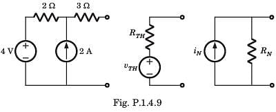
The value of the parameter are

Detailed Solution for Test: ESE Electrical - 6 - Question 2


1 Crore+ students have signed up on EduRev. Have you? Download the App
Test: ESE Electrical - 6 - Question 3

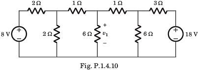
v1 = ?

Detailed Solution for Test: ESE Electrical - 6 - Question 3

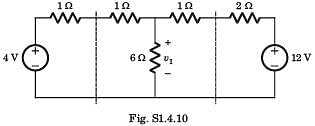
If we solve this circuit direct, we have to deal with three variable. But by simple manipulation variable can be reduced to one. By changing the LHS and RHS in Thevenin equivalent

Test: ESE Electrical - 6 - Question 4

In the circuit shown in fig. a steady state has been established before switch closed. The i(t) for t > 0 is

Detailed Solution for Test: ESE Electrical - 6 - Question 4

Test: ESE Electrical - 6 - Question 5

The switch is closed after long time in the circuit of fig. The v(t) for t > 0 is

Detailed Solution for Test: ESE Electrical - 6 - Question 5


Test: ESE Electrical - 6 - Question 6

In the circuit of fig. i(0) = 1A and v(0) = 0. The current i(t) for t > 0 is

Detailed Solution for Test: ESE Electrical - 6 - Question 6


Test: ESE Electrical - 6 - Question 7

Vx = ?

Detailed Solution for Test: ESE Electrical - 6 - Question 7

Let Vo be the voltage across current source

Vo(20 + j10) - (20 + j40) Vx = j600


Test: ESE Electrical - 6 - Question 8

The T-parameters of a 2-port network are 

If such two 2-port network are cascaded, the z –parameter for the cascaded network is

Detailed Solution for Test: ESE Electrical - 6 - Question 8

 ​

   .......(i)
 ........(ii)

Test: ESE Electrical - 6 - Question 9

n a balanced three-phase system-delta load, if we assume the line voltage is VRY = V∠0⁰ as a reference phasor. Then the source voltage VBR is?

Detailed Solution for Test: ESE Electrical - 6 - Question 9

As the line voltage VRY = V∠0⁰ is taken as a reference phasor. Then the source voltage VBR is V∠-240⁰.

Test: ESE Electrical - 6 - Question 10

The three impedances Z1 = 20∠30⁰Ω, Z2 = 40∠60⁰Ω, Z3 = 10∠-90⁰Ω are delta-connected to a 400V, 3 – Ø system. Find the power in the B phase.

Detailed Solution for Test: ESE Electrical - 6 - Question 10

The term power is defined as the product of square of current and the impedance. So the power in the B phase = 402 x 0 = 0W.

Test: ESE Electrical - 6 - Question 11

Find the magnetic force when a charge 3.5C with flux density of 4 units is having a velocity of 2m/s.

Detailed Solution for Test: ESE Electrical - 6 - Question 11

The magnetic force is given by F = q(v x B), where q = 3.5C, v = 2m/s and B = 4 units. Thus we get F = 3.5(2 x 4) = 28 units.

Test: ESE Electrical - 6 - Question 12

Find the electric field when the velocity of the field is 12m/s and the flux density is 8.75 units.

Detailed Solution for Test: ESE Electrical - 6 - Question 12

The electric field intensity is the product of the velocity and the magnetic flux density ie, E = v x B = 12 x 8.75 = 105 units.

Test: ESE Electrical - 6 - Question 13

The unit impulse response of a linear time invariant system is the unit step function u(t) for t > 0, the response of the system to an excitation e-at u(t), a > 0 will be

Detailed Solution for Test: ESE Electrical - 6 - Question 13

Given: h(t) = u(t)
x(t) = e–at u(t)

∴ Y(s) = X(s) H(s)
=   

y(t) = 1/a (1 – e– at) u(t)

Test: ESE Electrical - 6 - Question 14

What is the partial fraction expansion of the proper function X(z)= 1/(1-1.5z-1+0.5z-2 )? 

Detailed Solution for Test: ESE Electrical - 6 - Question 14

First we eliminate the negative powers of z by multiplying both numerator and denominator by z2.
Thus we obtain X(z) = z2/(z2-1.5z + 0.5)
The poles of X(z) are p1 = 1 and p2 = 0.5. Consequently, the expansion will be
(X(z))/z = z/((z-1)(z-0.5)) = 2/((z-1) ) – 1/((z-0.5) )( obtained by applying partial fractions)
⇒ X(z)= 2z/(z-1)-z/(z-0.5).

Test: ESE Electrical - 6 - Question 15

What is the partial fraction expansion of X(z)= (1+z-1)/(1-z-1+0.5z-2 )? 

Detailed Solution for Test: ESE Electrical - 6 - Question 15

To eliminate the negative powers of z, we multiply both numerator and denominator by z2. Thus,
X(z)=(z(z+1))/(z-2-z+0.5)
The poles of X(z) are complex conjugates p1=0.5+0.5j and p2=0.5-0.5j
Consequently the expansion will be
X(z)= (z(0.5-1.5j))/(z-0.5-0.5j) + (z(0.5+1.5j))/(z-0.5+0.5j).

Test: ESE Electrical - 6 - Question 16

Determine the Laplace transform of given signal.
Q. 

Detailed Solution for Test: ESE Electrical - 6 - Question 16


Test: ESE Electrical - 6 - Question 17

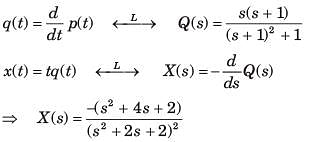
Determine the time signal x(t) corresponding to given X (s) and choose correct option.
Q. 

Detailed Solution for Test: ESE Electrical - 6 - Question 17


Test: ESE Electrical - 6 - Question 18

The Fourier series coefficient of a periodic signal, x(t) is defined as

Which of the following statement is correct.

Detailed Solution for Test: ESE Electrical - 6 - Question 18

CASE 1: Let us assume that x(t) is real, then x(t) = x*(t). This implies that for x(t) to be real, ak = a*-k. Since this is not true. So, x(t) is not real.
CASE 2: Let us assume that x(t) is even, then x(t) = x(-t) and ak = a–k. Since this is true for this case, hence x(t) is even.
CASE 3: Let us assume

Therefore,

Since bk is not even, So, g(t) is not even.

Test: ESE Electrical - 6 - Question 19

Find the value of A and B for signal, g(t) = Ay (Bt), such that y(t) = x (t) * h(t) and g(t) = x(3t) * h (3t) is

Detailed Solution for Test: ESE Electrical - 6 - Question 19

We know that,

Given form is,

So, we can write it as,

Comparing both equations, we get,

Taking Inverse Fourier Transform,

Comparing with given signal, g(t) = Ay (Bt)
A = 1/3 and B = 3

Test: ESE Electrical - 6 - Question 20

In the question, the FS coefficient of time-domain signal have been given. Determine the corresponding time domain signal and choose correct option.


Detailed Solution for Test: ESE Electrical - 6 - Question 20


Test: ESE Electrical - 6 - Question 21

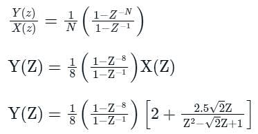
An input signal x(t) = 2 + 5sin⁡(100πt) is sampled with a sampling frequency of 400 Hz and applied to the system whose transfer function is represented by

where, N represents the number of samples per cycle. The output y[n] of the system under steady state is

Detailed Solution for Test: ESE Electrical - 6 - Question 21

Final value theorem,

Calculation:
We have:

and x(t) = 2 + 5sin(100πt)
sampling frequency, fs = 400 Hz
put t = nTs, the output of the sampling process is,
x(nTs) = 2 + sin(100πnTs)
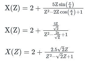
x(nTs) = 2 + 5 sin

where,
ω0 = π/4

The z-transform of x(n) is,


From equation (i)

using final value theorem,


y(∞) = 0

Test: ESE Electrical - 6 - Question 22

If we split the N point data sequence into two N/2 point data sequences f1(n) and f2(n) corresponding to the even numbered and odd numbered samples of x(n) and F1(k) and F2(k) are the N/2 point DFTs of f1(k) and f2(k) respectively, then what is the N/2 point DFT X(k) of x(n)? 

Detailed Solution for Test: ESE Electrical - 6 - Question 22

From the question, it is given that
f1(n)=x(2n)
f2(n)=x(2n+1) ,n=0,1,2…N/2-1


X(k) = F1(k)+WNkNk F2(k)

Test: ESE Electrical - 6 - Question 23

Which of the following defines the rectangular window function of length M-1?

Detailed Solution for Test: ESE Electrical - 6 - Question 23

We know that the rectangular window of length M-1 is defined as
w(n)= 1, n=0,1,2…M-1
=0, else where.

Test: ESE Electrical - 6 - Question 24

How many memory locations are used for storage of the output point of a sequence of length M in direct form realization?

Detailed Solution for Test: ESE Electrical - 6 - Question 24
  • The direct form realization follows immediately from the non-recursive difference equation given by 
  • We observe that this structure requires M-1 memory locations for storing the M-1 previous inputs.
Test: ESE Electrical - 6 - Question 25

For the system shown in figure below,  is equal to (where, T = closed loop transfer function)

Detailed Solution for Test: ESE Electrical - 6 - Question 25

The CLTF is

Test: ESE Electrical - 6 - Question 26

Use mason’s gain formula to find the transfer function of the following signal flow graph:

Detailed Solution for Test: ESE Electrical - 6 - Question 26

Using mason’s gain formula transfer functionThe given signal flow graph can be represented by the transfer function:

T(s) = (abcd + efg) / (1 - cd - fg - cdfg)

We can rearrange this equation as follows:

T(s) = (abcd + efg) / (1 - (cd + fg) - cdfg)

We need to find the transfer function using Mason's Gain formula. Mason's Gain formula is given by:

T(s) = Σ(Pk * Δk) / Δ

where T(s) is the transfer function, Pk is the gain of the kth forward path, Δk is the determinant of the kth forward path, and Δ is the overall determinant.

Step 1: Identify the forward paths and their gains
- Forward path 1: abcd, gain = abcd
- Forward path 2: efg, gain = efg

Step 2: Identify the loops and their gains
- Loop 1: cd, gain = cd
- Loop 2: fg, gain = fg

Step 3: Calculate the overall determinant (Δ)
Δ = 1 - (sum of loop gains) + (sum of product of gains of non-touching loops) - ...
Δ = 1 - (cd + fg) + (0) - ...
Δ = 1 - cd - fg

Step 4: Calculate the determinants for each forward path (Δk)
Δ1 = 1 - fg (since loop 1 touches forward path 1)
Δ2 = 1 - cd (since loop 2 touches forward path 2)

Step 5: Calculate the transfer function using Mason's Gain formula
T(s) = (abcd * Δ1 + efg * Δ2) / Δ
T(s) = (abcd * (1 - fg) + efg * (1 - cd)) / (1 - cd - fg)

Now, let's compare the given options with the calculated transfer function:

Option A: abcd + efg / (1 - cd - fg - cdfg)
Option B: abcd(1 - fg) + efg(1 - cd) / (1 - cd - fg)
Option C: abef + bcd / (1 - cd - fg - cdfg)
Option D: adcdefg / (1 - cd - fg - cdfg)

The correct answer is Option B, as it matches the calculated transfer function. from signal flow graph can be calculated which relates the forward path gain to the various paths and loops.

Test: ESE Electrical - 6 - Question 27

Consider the unity feedback system shown below:​

The settling time of the resulting second order system for 2% tolerance band will be

Detailed Solution for Test: ESE Electrical - 6 - Question 27

The characteristic equation of the given closed loop system is

Comparing above equation with

Thus, setting time for 2% tolerance band is

or, 

Test: ESE Electrical - 6 - Question 28

Consider the following characteristic equation of a system:
s3 + 2Ks2 + (K+ 2) s+ 4 = 0
Which one of the following is correct?

Detailed Solution for Test: ESE Electrical - 6 - Question 28

Given characteristic equation is,
s2 + 2Ks2 + (K + 2)s + 4 = 0
Routh’s array is:

For stability, 2K > 0 or K > 0

Now, K2 + 2K - 2 = 0 or, K = 0.73, -2.73
For K > 0.73, K2 + 2 K - 2 > 0
(since K should be > 0)
Hence, system will be stable if K > 0.73.

Test: ESE Electrical - 6 - Question 29

The open loop transfer function of a unity feedback control system is given by

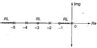
The breakaway point in its root locus will lie between

Detailed Solution for Test: ESE Electrical - 6 - Question 29


Here, P = 4,Z = 1, P - Z = 3
No. of branches of RL terminating at zero = 1.
No. of branches of RL terminatina at infinity = 3

Since out of the given option, real axis between s = -2 and s = -4 is only a part of root locus, therefore breakaway point will lie between -2 and -4.

Test: ESE Electrical - 6 - Question 30

Polar plot of G(s) = 1/(1+Ts) is a

Detailed Solution for Test: ESE Electrical - 6 - Question 30

Given, G(s) = 1/(1+Ts)
It is a type-0 and order-1 system, therefore its polar-plot will be as shown below.

Hence, the polar plot will be semicircular in shape.

View more questions
12 tests
Information about Test: ESE Electrical - 6 Page
In this test you can find the Exam questions for Test: ESE Electrical - 6 solved & explained in the simplest way possible. Besides giving Questions and answers for Test: ESE Electrical - 6, EduRev gives you an ample number of Online tests for practice

Top Courses for Electrical Engineering (EE)

Download as PDF

Top Courses for Electrical Engineering (EE)