Electrical Engineering (EE) Exam  >  Electrical Engineering (EE) Tests  >  Engineering Services Examination (ESE) Mock Test Series 2024  >  Test: ESE Electrical - 7 - Electrical Engineering (EE) MCQ

Test: ESE Electrical - 7 - Electrical Engineering (EE) MCQ


Test Description

30 Questions MCQ Test Engineering Services Examination (ESE) Mock Test Series 2024 - Test: ESE Electrical - 7

Test: ESE Electrical - 7 for Electrical Engineering (EE) 2024 is part of Engineering Services Examination (ESE) Mock Test Series 2024 preparation. The Test: ESE Electrical - 7 questions and answers have been prepared according to the Electrical Engineering (EE) exam syllabus.The Test: ESE Electrical - 7 MCQs are made for Electrical Engineering (EE) 2024 Exam. Find important definitions, questions, notes, meanings, examples, exercises, MCQs and online tests for Test: ESE Electrical - 7 below.
Solutions of Test: ESE Electrical - 7 questions in English are available as part of our Engineering Services Examination (ESE) Mock Test Series 2024 for Electrical Engineering (EE) & Test: ESE Electrical - 7 solutions in Hindi for Engineering Services Examination (ESE) Mock Test Series 2024 course. Download more important topics, notes, lectures and mock test series for Electrical Engineering (EE) Exam by signing up for free. Attempt Test: ESE Electrical - 7 | 150 questions in 180 minutes | Mock test for Electrical Engineering (EE) preparation | Free important questions MCQ to study Engineering Services Examination (ESE) Mock Test Series 2024 for Electrical Engineering (EE) Exam | Download free PDF with solutions
Test: ESE Electrical - 7 - Question 1

Calculate the value of RL across A and B.

Detailed Solution for Test: ESE Electrical - 7 - Question 1

On shorting the voltage sources:
RL=3||2+4||5.

Test: ESE Electrical - 7 - Question 2

Calculate the maximum power transferred.

Detailed Solution for Test: ESE Electrical - 7 - Question 2

On shorting the voltage sources:
RL = 3||2+4||3 
= 1.20 + 1.71
= 2.91 ohm.
The two nodal equations are:
(VA-10)/3 + VA/2 = 0
(VB-20)/4 + VB/3 = 0
On solving the two equations, we get VA=4V, VB=8.571V.
VAB = VA - VB 
= 4V – 8.571V 
= -4.57V.
Eth = 4.57V
The maximum power transferred = Eth2/4RL. Substituting the given values in the formula, we get Pmax = 1.79W

1 Crore+ students have signed up on EduRev. Have you? Download the App
Test: ESE Electrical - 7 - Question 3

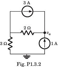
va = ?

Detailed Solution for Test: ESE Electrical - 7 - Question 3

va = 2(3 + 1) + 3 (1) = 11 V

Test: ESE Electrical - 7 - Question 4

In the circuit of fig. a steady state has been established before switch closed. The i(t) for t > 0 is

Detailed Solution for Test: ESE Electrical - 7 - Question 4


α = Wo, critically damped response

s = -2, -2
i(t) = (A + Bt)e-2t, A = -2

At t = 0. ⇒ B = -2

Test: ESE Electrical - 7 - Question 5

A resistance of 7 ohm is connected in series with an inductance of 31.8mH. The circuit is connected to a 100V 50Hz sinusoidal supply. Calculate the current in the circuit.

Detailed Solution for Test: ESE Electrical - 7 - Question 5

X= 2*π*f*L = 10 ohm
Z= (R2+XL2)
Therefore the total impedance
Z = 12.2 ohm
V = IZ
therefore,
I= V/Z = 100/12.2 = 8.2A

Test: ESE Electrical - 7 - Question 6

The equivalent circuit of the capacitor shown below is:

Detailed Solution for Test: ESE Electrical - 7 - Question 6

Due to initial condition, at t = 0 capacitor will act as a constant voltage source (at t = 0, capacitor acts as short-circuit). Hence, option (d) is correct.

Test: ESE Electrical - 7 - Question 7

Determine the complex power for hte given valuesin question.

Q = 2000 VAR, pf =09. (leading)

Detailed Solution for Test: ESE Electrical - 7 - Question 7

pf = cos θ = 0.9 ⇒ θ = 25.84°
Q = S sin θ ⇒ 

Test: ESE Electrical - 7 - Question 8

[Y] = ?

​ ​ ​

Detailed Solution for Test: ESE Electrical - 7 - Question 8


Test: ESE Electrical - 7 - Question 9

If the load impedance is Z∠Ø, the current (IR) is?A:

Detailed Solution for Test: ESE Electrical - 7 - Question 9

As the load impedance is Z∠Ø, the current flows in the three load impedances and the current flowing in the R impedance is IR = VBR∠0⁰/Z∠Ø = (V/Z)∠-Ø.

Test: ESE Electrical - 7 - Question 10

The three impedances Z1 = 20∠30⁰Ω, Z2 = 40∠60⁰Ω, Z3 = 10∠-90⁰Ω are delta-connected to a 400V, 3 – Ø system. Find the power in the R phase.

Detailed Solution for Test: ESE Electrical - 7 - Question 10

The term power is defined as the product of square of current and the impedance. So the power in the R phase = 202 x 17.32 = 6928W.

Test: ESE Electrical - 7 - Question 11

Find the Lorentz force of a charge 2.5C having an electric field of 5 units and magnetic field of 7.25 units with a velocity 1.5m/s.

Detailed Solution for Test: ESE Electrical - 7 - Question 11

The Lorentz force is given by F = qE + q(v x B), it is the sum of electric and magnetic force. On substituting q = 2.5, E = 5, v = 1.5 and B = 7.25, F = 2.5(5) + 2.5(1.5 x 7.25) = 39.68 units.

Test: ESE Electrical - 7 - Question 12

The force on a conductor of length 12cm having current 8A and flux density 3.75 units at an angle of 300 is

Detailed Solution for Test: ESE Electrical - 7 - Question 12

The force on a conductor is given by F = BIL sin θ, where B = 3.75, I = 8, L = 0.12 and θ = 300. We get F = 3.75 x 8 x 0.12 sin 30 = 1.8 units.

Test: ESE Electrical - 7 - Question 13

A system with an input x(t) and output y(t) is described by the relation: y(t) = tx(t). This system is

Detailed Solution for Test: ESE Electrical - 7 - Question 13

y(t) = tx(t)
y1(t) = t.x1(t) = r1(t)
y2(t) = tx2(t) = r2(t)
y1(t) + y2(t) = t(x1(t) + x2(t))
= r1(t) + r2(t)    ∴ linear
y(t) = t.x(t)
y( t - to) = (t - to) x ( t - to)
and for delayed input signal,
y(t) = t x (t - to)
y(t) ≠ y( t-to)
∴ Time varying signal

Test: ESE Electrical - 7 - Question 14

What is the partial fraction expansion of X(z)=1/((1+z-1 )(1-z-1)2)? 

Detailed Solution for Test: ESE Electrical - 7 - Question 14

First we express X(z) in terms of positive powers of z, in the form X(z)=z3/((z+1)〖(z-1)〗2 )
X(z) has a simple pole at z=-1 and a double pole at z=1. In such a case the approximate partial fraction expansion is
(X(z))/z = z2/((z+1)〖(z-1)〗2 ) =A/(z+1) + B/(z-1) + C/〖(z-1)〗2
On simplifying, we get the values of A, B and C as 1/4, 3/4 and 1/2 respectively.
Therefore, we get X(z)= z/(4(z+1)) + 3z/(4(z-1)) + z/(2〖(z-1)〗2 ) .

Test: ESE Electrical - 7 - Question 15

What is the inverse z-transform of X(z)= 1/(1-1.5z-1+0.5z-2 ) if ROC is |z|<0.5?   

Detailed Solution for Test: ESE Electrical - 7 - Question 15

The partial fraction expansion for the given X(z) is
X(z)= 2z/(z-1)-z/(z-0.5)
In case when ROC is |z|<0.5,the signal is anti causal. Thus both the terms in the above equation are anti causal terms. So, if we apply inverse z-transform to the above equation we get x(n)= [-2+0.5n]u(-n-1).

Test: ESE Electrical - 7 - Question 16

Determine the time signal x(t) corresponding to given X (s) and choose correct option.

Detailed Solution for Test: ESE Electrical - 7 - Question 16


Test: ESE Electrical - 7 - Question 17

Determine the time signal x(t) corresponding to given X (s) and choose correct option.

Detailed Solution for Test: ESE Electrical - 7 - Question 17


Test: ESE Electrical - 7 - Question 18

For a signal u(sint); Fourier series is having

Detailed Solution for Test: ESE Electrical - 7 - Question 18

Given x(t) = u(sint)
Drawing waveform

We know for waveform like y(t) shown

DC component is zero and have sine odd harmonics.
Performing upward shift in y(t) by adding dc value of 0.5, then
x(t) = y(t) + 0.5
So, x(t) → DC + sine odd harmonics

Test: ESE Electrical - 7 - Question 19

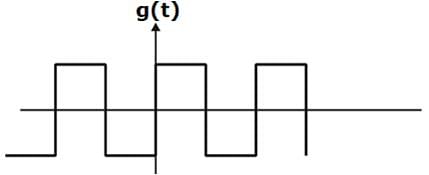
The ratio of powers present in 3rd harmonic to 5th harmonic for a square periodic signal.

Detailed Solution for Test: ESE Electrical - 7 - Question 19

We know that from Fourier Series coefficient of square periodic signal, power is proportional to (1/n2).


Test: ESE Electrical - 7 - Question 20

In the question, the FS coefficient of time-domain signal have been given. Determine the corresponding time domain signal and choose correct option.

X[k] As shown in fig. , ωo = 2π

Detailed Solution for Test: ESE Electrical - 7 - Question 20

Test: ESE Electrical - 7 - Question 21

The Nyquist sampling interval, for the signal sinc(700t) + sinc(500t) is:

Detailed Solution for Test: ESE Electrical - 7 - Question 21

Concept:
Nyquist rate: The minimum sampling rate is often called the Nyquist rate. The Nyquist sampling rate is two times the highest frequency of the input or message signal.
fs = 2fm
Where,
fs is the minimum sampling frequency or Nyquist rate
fm is the highest frequency of the input or message signal.
Calculation:
sinc(700t) + sinc(500t)

f1 = 700π/2π = 350 Hz
f2 = 500π/2π = 250 Hz
fm = max (f1, f2) = max (350, 250) = 350 Hz
Sampling frequency,
fs = 2fm = 2 × 350 = 700 Hz
Sampling time period = 1/700 sec

Test: ESE Electrical - 7 - Question 22

If X(k) is the N/2 point DFT of the sequence x(n), then what is the value of X(k+N/2)? 

Detailed Solution for Test: ESE Electrical - 7 - Question 22

We know that, X(k) = F1(k)+WNk F2(k)
We know that F1(k) and F2(k) are periodic, with period N/2, we have F1(k+N/2)= F1(k) and F2(k+N/2)= F2(k). In addition, the factor WNk+N/2= -WNk.
Thus we get, X(k+N/2)= F1(k)- WNk F2(k).

Test: ESE Electrical - 7 - Question 23

What is the condition of M, if the structure according to the direct form is as follows?

Detailed Solution for Test: ESE Electrical - 7 - Question 23
  • When the FIR system has linear phase, the unit sample response of the system satisfies either the symmetry or asymmetry condition, h(n)= ±h(M-1-n)
  • For such a system the number of multiplications is reduced from M to M/2 for M even and to (M-1)/2 for M odd. Thus for the structure given in the question, M is odd.
Test: ESE Electrical - 7 - Question 24

By combining two pairs of poles to form a fourth order filter section, by what factor we have reduced the number of multiplications?

Detailed Solution for Test: ESE Electrical - 7 - Question 24
  • We have to do 3 multiplications for every second order equation.
  • So, we have to do 6 multiplications if we combine two second order equations and we have to perform 3 multiplications by directly calculating the fourth order equation.
  • Thus the number of multiplications are reduced by a factor of 50%.
Test: ESE Electrical - 7 - Question 25

In control system, the feedback

Detailed Solution for Test: ESE Electrical - 7 - Question 25
  • In a control system, feedback refers to the process of measuring the output of the system and comparing it to the desired or reference input. This information is then used to adjust the system's behavior in order to reduce any error between the output and the desired input. By continuously monitoring and correcting the system's output, feedback helps to minimize the error and improve the system's performance.
  • Additionally, feedback also helps to reduce the sensitivity of the system to parameter variations. In a control system, there are often uncertainties or variations in the system's parameters (such as variations in component values or environmental conditions). These parameter variations can affect the system's behavior and introduce errors. However, by using feedback, the control system can continuously adapt and adjust its response to compensate for these variations, thus reducing the sensitivity of the system to parameter changes.
  • Therefore, the correct answer is C: "reduces the error and the sensitivity of the system to parameter variation."
Test: ESE Electrical - 7 - Question 26

Loop which do not possess any common node are said to be ___________ loops.

Detailed Solution for Test: ESE Electrical - 7 - Question 26

Loop is the part of the network in which the branch starts from the node and comes back to the same node and non touching loop must not have any node in common.

Test: ESE Electrical - 7 - Question 27

For a control system, the Laplace transform of error signal e(t) is given by . The steady state value of the error will be

Detailed Solution for Test: ESE Electrical - 7 - Question 27

Given, 


(Using final value theorem) 
or, 

Test: ESE Electrical - 7 - Question 28

For which of the following values of K, the feedback system shown in the below figure is stable?

Detailed Solution for Test: ESE Electrical - 7 - Question 28

The characteristic equation is
1 + G (s) H (s) = 0
or, 


or, s3 + 10s2 + (21 + K )s + 13 K= 0

For stability, 13K > 0 or K > 0
Also, 

or, K < 70
Hence, 0 < K< 70 (For stability).

Test: ESE Electrical - 7 - Question 29

The characteristic equation of a closed loop control system is given by:
s+ 2s +10 + K(s2 + 6s + 10) = 0
The angle of asymptotes for the root loci for K ≥ 0 are given by

Detailed Solution for Test: ESE Electrical - 7 - Question 29

Given, s2 + 2s + 10 + K(s2 + 6s + 10) = 0

Here, number of open loop poles, P = 2. Number of open loop zero, Z = 2
∴ P - Z = 0.
Angle of asymptotes are given by:

Sines P - Z = 0, therefore there are no angle of asymptotes for the root locus of the given system.

Test: ESE Electrical - 7 - Question 30

Consider the following statements related to frequency domain analysis:

  1. The cut-off rate is the slope of the log magnitude curve near the cut-off frequency.
  2. The bandwidth is defined as the band of frequencies lying between 3 dB points.
  3. Higher the value of resonant frequency of the system, slower is the time response.
  4. The magnitude of resonant peak gives the information about the relative stability of the system.

Which of these statements is/are not correct?

Detailed Solution for Test: ESE Electrical - 7 - Question 30

The bandwidth is defined as the band of frequencies tying between-3 dB points. Hence, statement-2 is false.
Higher the value of resonant frequency of the system, faster is the time response. Hence, statement-3 is false.

View more questions
12 tests
Information about Test: ESE Electrical - 7 Page
In this test you can find the Exam questions for Test: ESE Electrical - 7 solved & explained in the simplest way possible. Besides giving Questions and answers for Test: ESE Electrical - 7, EduRev gives you an ample number of Online tests for practice

Top Courses for Electrical Engineering (EE)

Download as PDF

Top Courses for Electrical Engineering (EE)