Electronics and Communication Engineering (ECE) Exam  >  Electronics and Communication Engineering (ECE) Tests  >  MPPGCL JE Electronics Mock Test Series 2025  >  MPPGCL JE Electronics Mock Test - 1 - Electronics and Communication Engineering (ECE) MCQ

MPPGCL JE Electronics Mock Test - 1 - Electronics and Communication Engineering (ECE) MCQ


Test Description

30 Questions MCQ Test MPPGCL JE Electronics Mock Test Series 2025 - MPPGCL JE Electronics Mock Test - 1

MPPGCL JE Electronics Mock Test - 1 for Electronics and Communication Engineering (ECE) 2025 is part of MPPGCL JE Electronics Mock Test Series 2025 preparation. The MPPGCL JE Electronics Mock Test - 1 questions and answers have been prepared according to the Electronics and Communication Engineering (ECE) exam syllabus.The MPPGCL JE Electronics Mock Test - 1 MCQs are made for Electronics and Communication Engineering (ECE) 2025 Exam. Find important definitions, questions, notes, meanings, examples, exercises, MCQs and online tests for MPPGCL JE Electronics Mock Test - 1 below.
Solutions of MPPGCL JE Electronics Mock Test - 1 questions in English are available as part of our MPPGCL JE Electronics Mock Test Series 2025 for Electronics and Communication Engineering (ECE) & MPPGCL JE Electronics Mock Test - 1 solutions in Hindi for MPPGCL JE Electronics Mock Test Series 2025 course. Download more important topics, notes, lectures and mock test series for Electronics and Communication Engineering (ECE) Exam by signing up for free. Attempt MPPGCL JE Electronics Mock Test - 1 | 100 questions in 120 minutes | Mock test for Electronics and Communication Engineering (ECE) preparation | Free important questions MCQ to study MPPGCL JE Electronics Mock Test Series 2025 for Electronics and Communication Engineering (ECE) Exam | Download free PDF with solutions
MPPGCL JE Electronics Mock Test - 1 - Question 1

Which is the classification of drive according to dynamics and transients?

Detailed Solution for MPPGCL JE Electronics Mock Test - 1 - Question 1

The correct answer is option 4.

Classification of Electrical drive

1.)  On the basis of the operation

  • Continuous duty drives
  • Short-time duty drives
  • Intermittent duty drives

2.) On the basis of control

  • Manual
  • Semi-automatic
  • Automatic

3.) On the basis of machine connection

  • Individual drive
  • Group drive
  • Multi motor drive

4.) On the basis of dynamics and transients

  • Variable position control
  • Step speed control Reversible and non - reversible
  • Uncontrolled constant speed reversible and non - reversible
MPPGCL JE Electronics Mock Test - 1 - Question 2

In a semiconductor, Drift current is due to:

Detailed Solution for MPPGCL JE Electronics Mock Test - 1 - Question 2

Drift Current:

  • Drift current in the diode is the combined effect of movement of the minority charge carrier and majority charge carriers and also on the electric field applied to the diode.
  • Drift current is due to the motion of charge carriers when a force exerted on them by an electric field.
  • In the p-n junction diode, electrons are the majority charge carriers in the n-region and holes are the majority charge carriers in the p-region.
  • When an electric field is applied to the diode there is more number of covalent bonds break and the concentration of charge carriers also increases in both region (p-type, n-type), and hence they affect the drift current in the diode.

Drift current Idrift = Jdrift × A

Where, Jdrift = Drift current density

A = Area of semiconductor

Now, Jdrift = σ ⋅ E

= (nqμn + p.qμp)

σ = Conductivity

E = Electric field

⇒ Idr = (nq.μn + p.qμp) ⋅ E A,

n = Number of electrons in n region

p = Number of holes in p-region

q = Charge on electrons and holes

μp = Mobility of holes

μn = Mobility of electrons

Additional Information

Diffusion

1) Diffusion is a natural phenomenon.

2) The migration of charge carriers from higher concentration to lower concentration or from higher density to lower density is called diffusion.

3) Diffusion is mainly due to the concentration gradient and is always negative.

It is given by:

 for holes and

 for electrons.

Diffusion current is calculated by:

 -----(1)

where,

Dis hole diffusion constant in cm2/sec

and q is charge in Coulomb.

1 Crore+ students have signed up on EduRev. Have you? Download the App
MPPGCL JE Electronics Mock Test - 1 - Question 3

What will be the decimal number equivalent to the binary number (11001)2?

Detailed Solution for MPPGCL JE Electronics Mock Test - 1 - Question 3

Given:

Binary number = 11001

Calculation:

According to the question, we have

Converting the binary number to decimal number

⇒ Decimal number = 1 x 24 + 1 x 23 + 0 x 22 + 0 x 21 + 1 x 20

⇒ 16 + 8 + 0 + 0 + 1

⇒ 25

∴ 25 is the decimal equivalent of the binary number (11001)2

MPPGCL JE Electronics Mock Test - 1 - Question 4

The energy per bit Eb of ASK, PSK and FSK follow:

Detailed Solution for MPPGCL JE Electronics Mock Test - 1 - Question 4

For ASK:

The energy of bit 1, 

 and energy of bit 0, 

So, average energy per bit,


For PSK:

So, average energy per bit,


For FSK:

So, average energy per bit, 

Thus, we see: 

2EBASK  = EBPSK = EBFSK

MPPGCL JE Electronics Mock Test - 1 - Question 5
Shifting the register content to left by two bits can be used to implement
Detailed Solution for MPPGCL JE Electronics Mock Test - 1 - Question 5

1) Shift registers are sequential circuits that are used for storage or for the transfer of binary data.

2) The shift register takes the data present on the input and "shifts" it to the output once every clock cycle.

3) Every shift in the register content to the right by one-bit position is equivalent to dividing the original number by two 

4) Every shift in the register content to the left by one-bit position is equivalent to multiplying the original number by two.

This is explained with the help of the following Example:

Example:

Let the original content of a 4-bit right shift register is 0100 which is 4 in decimal, i.e.

(0100)2 = (4)10 

1). Shifting the content of the register to the left by two-bit position, the new content now becomes (10000)2, which is 16 in decimal, i.e.

(10000)2 = (16)10

Clearly, the original number is multiplied by 4. 

2). Shifting the content of the register to the right by one-bit position, the new content now becomes (0010)2, which is 2 in decimal, i.e.

(0010)2 = (2)10

Clearly, the original number is divided by 2. 

MPPGCL JE Electronics Mock Test - 1 - Question 6

If x[n] ↔ X(z), the z-transform of x[-n] will be:

Detailed Solution for MPPGCL JE Electronics Mock Test - 1 - Question 6

If , then the time-reversal property states that:

Proof:

Let –n = p, i.e.

n = -p

The z transform can now be written as:

The above can be written as:

= X(z-1)

MPPGCL JE Electronics Mock Test - 1 - Question 7

What will be the time response expression for a standard first order system having unit step function  as the input

Detailed Solution for MPPGCL JE Electronics Mock Test - 1 - Question 7

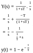
Let the standard first-order open-loop transfer function is:

then,

The closed-loop transfer function is:

 (assume unity negative feedback)

If input = unit step

Hence, option 2 is correct.

MPPGCL JE Electronics Mock Test - 1 - Question 8
If α = 0.98, Ico = 6 μA, & IB = 100 μA for a transistor, then the value of IC will be
Detailed Solution for MPPGCL JE Electronics Mock Test - 1 - Question 8

Concept:

For a BJT expression for collector current (Ic) is defined as-

IC = β IB + (1 + β) Ico

Where β = large signal current gain in CE mode of operation

IC = collector current

Ico = collector current when emitter is open

IB = Base current

α = large signal current gain in CB mode of operation

Relation between α and β:

Calculation:

Given data: α = 0.98

Ico = 6 μA

IB = 100 μA

Ic = β IB + (1 + β) Ico

Ic = 49 × 100 + (49 + 1) 6 μA

Ic = 5200 μA

[ ∵ 1 μA = 10-6 A

1 mA = 10-3 A

1 mA = 103 μA ] 

Ic = 5.2 mA

MPPGCL JE Electronics Mock Test - 1 - Question 9

What is the maximum data rate that can be transmitted using a QPSK modulation with a roll-off factor of 0.2 for a 36 MHz transponder?

Detailed Solution for MPPGCL JE Electronics Mock Test - 1 - Question 9

Concept:

QPSK is a modulation scheme that allows one symbol to transfer two bits of data. There are four possible two-bit numbers (00, 01, 10, 11).

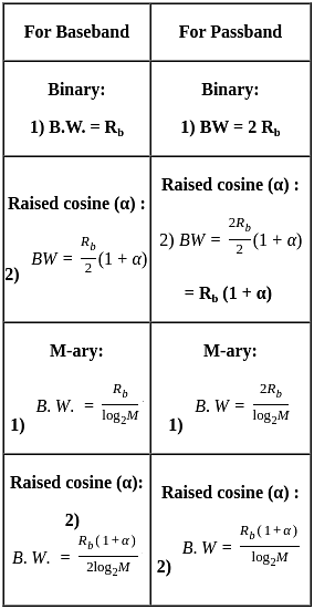
For bandpass transmission,

Bandwidth for M-ary PSK  

Given:

BW = 36 × 106 Hz

Roll-off factor = 0.2

Calculation:

Bandwidth for QPSK  

2 × 36 × 106 = 1.2 Rb

Rb = 72/1.2 Mbps 

= 60 Mbps

Important Point

MPPGCL JE Electronics Mock Test - 1 - Question 10

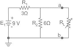
What is Thevenin's equivalent resistance for circuit shown in the given figure?
Detailed Solution for MPPGCL JE Electronics Mock Test - 1 - Question 10

Concept:

To calculate the Thevenin's equivalent resistance, independent sources are replaced by their internal resistance.

Given:

E1 = 9 Volt

Calculation:

To calculate Thevenin's equivalent resistance between a and b terminal E1 should be replaced by its internal resistance, hence it will short circuit.

RTh = Rab = 3 || 6

RTh = Rab = 2 ohm

MPPGCL JE Electronics Mock Test - 1 - Question 11
Which of the following is NOT a cursor control devices used in CAD systems
Detailed Solution for MPPGCL JE Electronics Mock Test - 1 - Question 11

Explanation:

CAD/CAM

  • CAD stands for Computer-Aided Design whereas CAM is the abbreviation for Computer-Aided Manufacturing.
  • CAD/CAM applications are used to both design a product and programme manufacturing processes, specifically, CNC machining.
  • CAD and CAM can be set up to create a direct link between the design and manufacture of a product. The drawing geometry is then used in the CAM program to generate instructions for the CNC machine tools employing stamping, cutting, burning, bending and other types of operations.

Hardware devices which are used in CAD/CAM application:

Cursor control devices:

  • Absolute touchpad
  • Thumbwheels
  • Mouse
  • Trackball
  • Light pen
  • Relative touchpad
  • Displacement joystick
  • Force joystick
MPPGCL JE Electronics Mock Test - 1 - Question 12

Schottky diodes drop about 0.3 V when conducting. This diode is connected in series with a resistor of 1 kΩ and forward biased with a battery of 1 V. Calculate the diode current.

Detailed Solution for MPPGCL JE Electronics Mock Test - 1 - Question 12

Analysis:


By KVL in the circuit,

-1 + 0.3 + 1000i = 0

1000i = 0.7

i = 

= 0.7 mA

MPPGCL JE Electronics Mock Test - 1 - Question 13

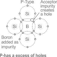
N-type materials are the type of materials formed by adding group _____ elements to the semiconductor crystals.

Detailed Solution for MPPGCL JE Electronics Mock Test - 1 - Question 13

Pentavalent impurities:

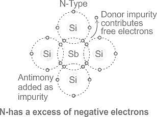
Impurity atoms with 5 valence electrons produce n-type semiconductors by contributing an extra electron.

This is as explained in the figure:

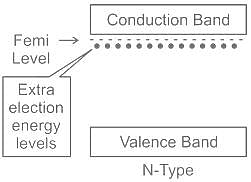
The energy band diagram for an  n-type semiconductor will be as shown:

Trivalent Impurities:

Impurity atoms with 3 valence electrons produce p-type semiconductors by producing a "hole" or an electron deficiency.

MPPGCL JE Electronics Mock Test - 1 - Question 14

A phase locked loop can be used to demodulate

Detailed Solution for MPPGCL JE Electronics Mock Test - 1 - Question 14
  • A phase-locked loop is a control system that generates an output signal whose phase is related to the phase of an input signal.
  • The circuit can track an input frequency or it can generate a frequency that is a multiple of the input frequency.
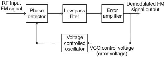
  • The basic elements of a PLL circuit are phase detector, a loop filter, voltage-controlled oscillator (VCO).

Applications:

  • FM demodulation
  • Clock generation
  • Frequency synthesizer
  • Clock recovery in a serial data link

Circuit diagram of FM demodulation using Phase Locked Loop is as shown:

MPPGCL JE Electronics Mock Test - 1 - Question 15

An ON-OFF controller is 

Detailed Solution for MPPGCL JE Electronics Mock Test - 1 - Question 15
  • On-Off control is the simplest form of feedback control.
  • An on-off controller simply drives the manipulated variable from fully closed to fully open depending on the position of the controlled variable relative to the setpoint.
  • A common example of on-off control is the temperature control in a domestic heating system.
  • It can be represented as a P controller.
MPPGCL JE Electronics Mock Test - 1 - Question 16

If contents of the accumulator in 8085 are 81 H and carry flag is '0', find accumulator contents after executing the instruction RRC?

Detailed Solution for MPPGCL JE Electronics Mock Test - 1 - Question 16

Concept:

In 8085 Instruction set, RRC stands for “Rotate Right Accumulator”. With the help of this instruction, we can rotate the Accumulator current content to the right by a 1-bit position. 

In this right rotation, the least significant bit will come out from the Accumulator and will be copied to the Cy bit in the flag register and also will be copied to the most significant bit position of the Accumulator.

The Cy flag is not involved in the rotation, and it is only an 8-bit rotation of Accumulator contents.

Only the Cy flag is affected by this instruction execution.

Analysis:

Given;

Content of accumulator = 81H → 1000 0001

Carry flag = 0

After execution of RRC instruction

Content of accumulator: 1100 0000 → C0 H

MPPGCL JE Electronics Mock Test - 1 - Question 17

Assuming zero initial conditions, the response y(t) of the system given below to a unit step input   is ____

Detailed Solution for MPPGCL JE Electronics Mock Test - 1 - Question 17

Concept:

Blocks which are cascaded are multiplied with their system in the frequency domain

Multiplication in the frequency domain corresponds to the Convolution in the time domain.

x(t) ∗ h(t) = y(t)

Laplace transform:  It comes in two variables, Bilateral and Unilateral.

The Bilateral Laplace transform offers insight into the nature of system characteristics such as Stability, causality, and frequency response.

The unilateral Laplace transform is a convenient tool for solving differential equations with initial conditions.

Analysis:

Let us consider the Laplace transform of h(t) is H(s)

Inverse Laplace transform is derived as shown

The above equation indicates that

H ( σ + jω ) is a Fourier transform of   

Hence the inverse Fourier transform of H ( σ + jω ) must be

. i.e,

A change of variable is performed by letting, s = σ + jω,

which also yields dω = ds/j, s → (σ – j∞ ) as:

 ω → - ∞ and s → (σ + j∞ ) as ω → ∞

Calculation:

 If we use integral formula the solution becomes very lengthy and it will be an iterative process.

So we use the simple property.

 ⋯ (i)

From the given question output equation will be multiplication since these are in the frequency domain.

comparing this with the above equation (i) the value of n = 1.

So the inverse Laplace transform y(t) will be tu(t).

MPPGCL JE Electronics Mock Test - 1 - Question 18

The question consists of two statements, one labeled as ‘Statement (I)’ and the other labeled as ‘Statement (II)’. You are to examine these two statements carefully and select the answers to these items using the codes given below:

Statement (I): The control system which operates on a time basis is an open-loop system

Statement (II): A field control d.c. motor is an example of an open-loop system.

Detailed Solution for MPPGCL JE Electronics Mock Test - 1 - Question 18

Open-loop system

  • A Control System which doesn’t have any feedback connected to it is called an Open Loop System.
  • These types of systems don’t depend upon their output i.e., in open-loop systems, the output is not used as a control variable for the system and it has no effect on the input. Open-loop systems are one way signal flow systems.
  • As these systems doesn’t contain any feedback i.e., the output is not fed back to the input, these are also known as Non-Feedback Systems.
  • The control system which operates on a time basis is an open-loop system.
  • For example, in automatic control of traffic, the time for each lamp (red, yellow, and green) is fixed.
  • The operation of each lamp does not depends upon the density of the traffic but depends upon the fixed time. Hence, the assertion is true. The reason is also true but, it is not the correct explanation of the assertion

Open-loop Motor Control
So for example, assume the DC motor controller as shown. The speed of rotation of the motor will depend upon the voltage supplied to the amplifier (the controller) by the potentiometer. The value of the input voltage could be proportional to the position of the potentiometer so there is no feedback so it is an open loop system.

Important Points

Advantages of Open-Loop Control System
The main advantages of the open-loop control system are listed below:

  • Open Loop Control Systems are very simple and easy to design.
  • These are considerably cheaper than other types of control systems.
  • The maintenance of an open-loop control system is very simple.
  • Generally, open-loop systems are stable up to some extent.
  • These types of systems are easy to construct and are convenient to use.

Disadvantages of Open-Loop Control System

The disadvantages of an open-loop system are:

  • The bandwidth of the open-loop control system is less.
  • The non-feedback system doesn’t facilitate the process of automation.
  • Open-loop systems are inaccurate in nature and also unreliable.
  • If their output is affected by some external disturbances, there is no way to correct them automatically as these are non-feedback systems.

Open Loop System Applications

We use open-loop control systems in many applications of our day-to-day lives. Some of the popular systems, which are designed based on the concept of open-loop control systems, are mentioned below:

  •  A field control d.c. motor
  • Washing Machine
  • Electric Bulb
  • Electric Hand Drier
  • Time-based Bread Toaster
  • Automatic Water Faucet
  • TV Remote Control
  • Electric Clothes Drier
  • Shades or Blinds on a window
  • Stepper Motor or Servo Motor
  • Inkjet Printers
  • Door Lock System
  • Traffic Control System
MPPGCL JE Electronics Mock Test - 1 - Question 19

Systems in which the output has no effect on the control action are called:

Detailed Solution for MPPGCL JE Electronics Mock Test - 1 - Question 19

Open-loop control system:

The open-loop control system can be described by a block diagram as shown in the figure below.

These are the systems in which the control action is independent of output.

Ex: Traffic signals, washing machine and bread toaster, systems having no sensor, etc.

Advantages:

  • Simple construction and design
  • Cost is less
  • Maintenance is easy
  • No problem of instability
  • Convenient to measure when the output is difficult to measure

Disadvantages:

  • These are less accurate, and their accuracy depends on the calibration.
  • Inaccurate results are obtained with parameter variations within the system.
  • Recalibration of the controller is required time to time to maintain accuracy.

Closed-loop control system:

The open-loop control system can be described by a block diagram as shown in the figure below.

These are the systems in which the control action depends on the output. These systems have a tendency to oscillate.

Ex: Temperature controllers, speed control of the motor, systems having sensors, etc.

Advantages:

  • More accurate
  • Non-linear distortions are less
  • Output is less sensitive to parameter changes within the system
  • Bandwidth increases

Disadvantages:

  • Design is complicated
  • More expensive
  • May become unstable, if there are malfunctions in the feedback.
MPPGCL JE Electronics Mock Test - 1 - Question 20
Which instrument is representing an integrating type instrument? 
Detailed Solution for MPPGCL JE Electronics Mock Test - 1 - Question 20

An energy meter is a type of integrating instrument.

Types of measuring instruments

The measuring instruments are divided into four major parts:

1.) Indicating Instrument

  • The indicating Instrument displays only the value of the electrical quantities per time of measurement.
  • This instrument gives the reading only when connected to the electrical supply. Otherwise, it goes to the zero position.
  • Ammeters, Voltmeters, Wattmeters, etc are examples of indicating instruments.

2.) Recording Instrument

  • The recording Instrument displays and records the reading of the electrical quantities per time of measurement.
  • This instrument is generally used in the generating Station and substation.
  • ECG and X-Rays are examples of recording instruments.

3.) Integrating Instrument

  • The Integrating Instrument displays, record, and add the numerical value of the reading of the electrical quantities per time of measurement.
  • The energy meter and Ampere-hour meter are examples of integrating instruments.

4.) Null Deflection Instrument

  • The Null Deflection Instrument shows the reading of the electrical quantities without the deflection angle at per time of measurement.
  • The potentiometer is an example of a null deflection instrument.
MPPGCL JE Electronics Mock Test - 1 - Question 21

​Which type of measurement cannot be done by potentiometer? 

Detailed Solution for MPPGCL JE Electronics Mock Test - 1 - Question 21

A potentiometer does not measure power.

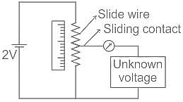
Potentiometer

  • A potentiometer is a three-terminal resistor with a sliding or rotating contact that forms an adjustable voltage divider.
  • It is used for the measurement of voltage, current, and resistance.
  • Potentiometers work by varying the position of a sliding contact across a uniform resistance.
  • In a potentiometer, the entire input voltage is applied across the whole length of the resistor, and the output voltage is the voltage drop between the fixed and sliding contact.
MPPGCL JE Electronics Mock Test - 1 - Question 22

Which of the following provide deflecting force for voltmeters only?

Detailed Solution for MPPGCL JE Electronics Mock Test - 1 - Question 22

Electrostatic type instrument:

  • The electrostatic type instrument uses a static electrical field to produce the deflecting torque.
  • These types of instruments are generally used for the measurement of high voltages.

Important Points

The principle of working of all electrical measuring instruments depends upon various effects of electric current or voltage as shown in the table given below.

MPPGCL JE Electronics Mock Test - 1 - Question 23

________ converts assembly language into machine language 

Detailed Solution for MPPGCL JE Electronics Mock Test - 1 - Question 23

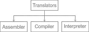
Assembler: The assembler is a program that translates the mnemonics/ assembly language into machine language (0’s and 1’s) and stores it into the memory.

Compiler: The compiler reads the whole program written in High-level language, first and translates into the object code that is executed by the microprocessor.

InterpreterAn interpreter reads one instruction at a time (of the program High-level language) produces its object code and executes the instruction before reading the next instruction.

MPPGCL JE Electronics Mock Test - 1 - Question 24

Which of the following layers in the ISO/OSI network model provides Error and Flow control at respective transmission levels?

Detailed Solution for MPPGCL JE Electronics Mock Test - 1 - Question 24

The correct answer is Transport and Data Link Layers.

Transport and Data Link Layers both provide error and flow control. 

Concept:-

Transport layer- The transport layer is responsible for the process to process delivery or end-to-end delivery. This layer provides flow control and error control. Working of the transport layer is based on port address. The transport layer used two protocols named TCP(transport control protocol) and UDP(user datagram protocol).

Note:- Flow control policy of TCP for data transfer is "TCP can accept out of order segments but always sends an inorder acknowledgment (ACK) ".

Application layer- This layer provides application services like HTTP, FTP, etc.

Network layer- In this layer routing algorithm, fragmentation concepts are implemented.

Data link layer-  It is used in the LAN(Local area network). This layer also provides flow control, error control, and the concept of framing as well.

The data link layer has various flow control policies:-

  • Stop and wait for ARQ(Automatic repeat request).
  • Go Back N ARQ.
  • Selective Repeat ARQ

Physical layer- This layer contains the physical electrical properties of the cable.

MPPGCL JE Electronics Mock Test - 1 - Question 25

'Calf' is related to 'Cow' in the same way as 'Kitten' is related to:

Detailed Solution for MPPGCL JE Electronics Mock Test - 1 - Question 25

As 'Calf' is the youngest of 'Cow' similarly 'Kitten' is the young one of 'Cat'.

MPPGCL JE Electronics Mock Test - 1 - Question 26

From which word does the monsoon taken

Detailed Solution for MPPGCL JE Electronics Mock Test - 1 - Question 26

The word monsoon comes from the Arabic word mausim, which means weather. Owing to the yearly appearance of torrential rain, indicating a marked shift in weather, mausim gradually became monsoon.

MPPGCL JE Electronics Mock Test - 1 - Question 27

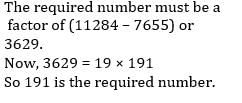
The numbers 11284 and 7655, when divided by a certain number of three digits, leave the same remainder. Find that number of three digits. 

Detailed Solution for MPPGCL JE Electronics Mock Test - 1 - Question 27

MPPGCL JE Electronics Mock Test - 1 - Question 28

The H.C.F. of two numbers is 96 and their L.C.M. is 1296. If one of the number is 864, the other is

Detailed Solution for MPPGCL JE Electronics Mock Test - 1 - Question 28

Using Rule 1 :
1st number × 2nd number = L.C. M. × H.C.F,
First number × Second number = HCF × LCM
⇒ 864 × Second number
= 96 × 1296 ⇒ Second number

MPPGCL JE Electronics Mock Test - 1 - Question 29

Directions to Solve

In each of the following questions find out the alternative which will replace the question mark.

Question -

Peacock : India :: Bear : ?

Detailed Solution for MPPGCL JE Electronics Mock Test - 1 - Question 29

As Peacock is the national bird of India, similarly Bear is the national animal of Russia.

MPPGCL JE Electronics Mock Test - 1 - Question 30
A wire is bent to form a square of side 22 cm. If the wire is rebent to form a circle, then its radius will be: 
Detailed Solution for MPPGCL JE Electronics Mock Test - 1 - Question 30

Given:

The side of the square = 22 cm

Formula used:

The perimeter of the square = 4 × a    (Where a = Side of the square)

The circumference of the circle = 2 × π × r     (Where r = The radius of the circle)

Calculation:

Let us assume the radius of the circle be r

⇒ The perimeter of the square = 4 × 22 = 88 cm

⇒ The circumference of the circle = 2 × π ×  r

⇒ 88 = 2 × (22/7) × r

⇒ 

⇒ r = 14 cm

∴ The required result will be 14 cm.

View more questions
10 tests
Information about MPPGCL JE Electronics Mock Test - 1 Page
In this test you can find the Exam questions for MPPGCL JE Electronics Mock Test - 1 solved & explained in the simplest way possible. Besides giving Questions and answers for MPPGCL JE Electronics Mock Test - 1, EduRev gives you an ample number of Online tests for practice

Top Courses for Electronics and Communication Engineering (ECE)

Download as PDF

Top Courses for Electronics and Communication Engineering (ECE)