Test: Electronics - 3 - Physics MCQ
20 Questions MCQ Test GATE Physics Mock Test Series 2025 - Test: Electronics - 3

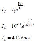
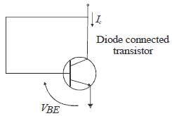
For an n-p-n transistor connected as shown in figure VBE = 0.7 volts. Given that reverse saturation current of the junction at room temperature 300° AT is 10-13 A. the emitter current is

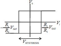
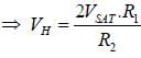
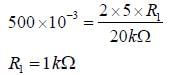
In the bistable circuit shown in the figure, the ideal OP- Amp lias saturation levels of ± 5 V. The value of R1 (in kΩ) that gives a hysteresis width of 500 mV is__________
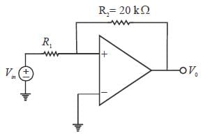
(Answer should be an integer)
(Answer should be an integer)
| 1 Crore+ students have signed up on EduRev. Have you? Download the App |
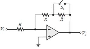
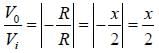
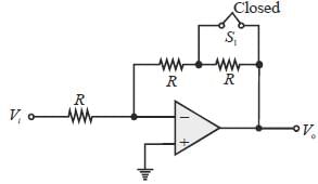
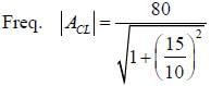
Let the magnitude of the gain in the inverting Op-Amp circuit shown be x with switch S1 open. When the switch is closed, the magnitude of gain becomes.

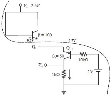
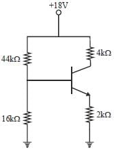
Consider the circuit shown in the figure. Assuming VBE1 = VEB2 = 0.7V, the value of the dc voltage VC2 (in volt) is ___________ .
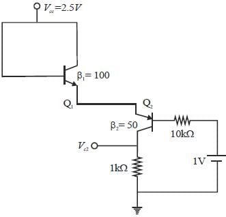
(Round off to one decimal place)
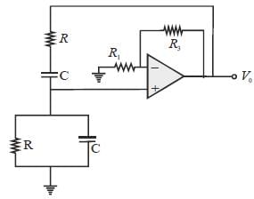
A Wein bridge oscillator is shown in figure, which of the following statements are true, if 'f' is the frequency of oscillation?

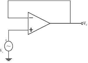
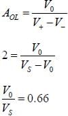
In a voltage follower op-amp circuit, find the closed loop gain V0/Vs if the open loop gain = 2
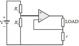
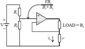
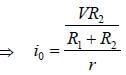
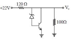
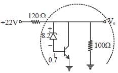
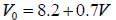
In the shunt regulator shown below, the Vz 8.2 V and VBE = 0.7 V. The regulated output voltage V0 is

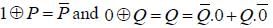
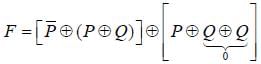
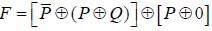
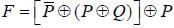
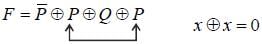
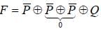
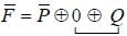
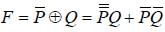
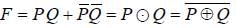
Let  denote the Exclusive OR (XOR) operation. Let '1' and '0' denote the binary constants. Consider the following Boolean expression for F over two variables P and Q :

The equivalent expression for F is


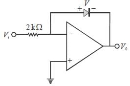
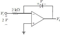
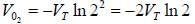
In the Op-Amp circuit shown, assume that the diode current follows the equation I = Is exp (V/VT). For V, = 2V, V0 = V01 and for Vi = 4V, V0 = V02, The relationsliip between V01 and V02 is


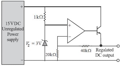
A regulated power supply, shown in figure below, lias an unregulated input (UR) of 15 volts and generates a regulated ouput. Use the component values shown in the figure.
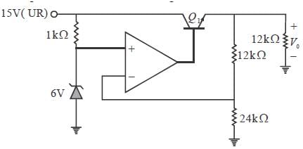
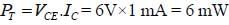
The power dissipation across the transistor Q1 shown in the figure is
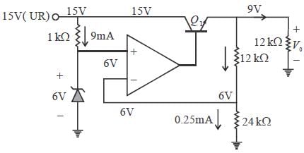

The output voltage of the regulated power supply shown in figure is
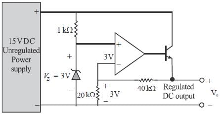


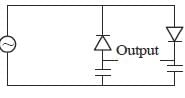
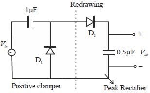
In the circuit shown, assume that diodes D1 and D2 are ideal. In the steady-state condition, the average voltage Vab (in Volts) across the 0.5 μF capacitor is
(Answer should be an integer)
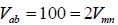
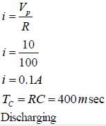
The figure shows a half-wave rectifier. The diode D is ideal. The average steady state current (inAmperes) through the diode is approximately____________
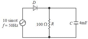
(Answer should be an integer)
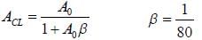
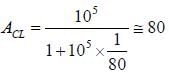
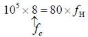
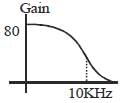
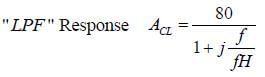
The amplifier circuit shown in the figure is implemented using a compensated operational amplier (OP-Amp), and has an open-loop voltage gain, A0 = 105 V/V and an open-loop cut-off frequency, fc = 8 Hz.

The voltage gain of the amplifier at 15 kHz. in V/V, is_______________
(Round off to two decimal places)


Consider the circuit shown in the figure Assume base-to-emitter voltage VBE - 0.8 V. and common base current gain(α) of the transistor is unity.
The value of the collector-to-emitter voltage VCE(in volts) is_________________.
(Answer should be an integer)

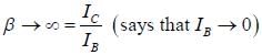


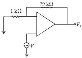
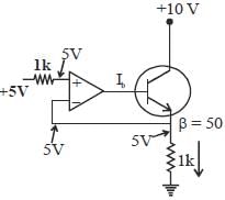
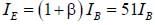
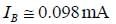
For the given circuit, value of the base current ( Ib) of the npn transistor will be___________mA.
(β is the current gain and assume Op-Amp as ideal).
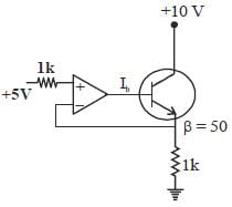
(Round off to three decimal places)

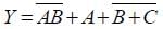
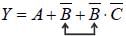
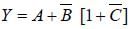
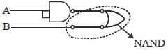
Transform the following logic circuit (without expressing its switching function) into an equivalent logic circuit that employs only NAND gates each with 2-inputs.

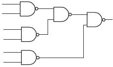
The number ofNAND sate required to implement y = 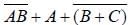 is__________
(Answer should be an integer)

|
1 docs|34 tests
|


Important Questions for Electronics - 3
Electronics - 3 MCQs with Answers
Online Tests for Electronics - 3 GATE Physics Mock Test Series 2025
|
© EduRev
|
Education Revolution
|


|


