Analog Electronics - 1 - Free MCQ Test with solutions for GATE EE and Digital
MCQ Practice Test & Solutions: Analog Electronics - 1 (10 Questions)
You can prepare effectively for Electrical Engineering (EE) Analog and Digital Electronics with this dedicated MCQ Practice Test (available with solutions) on the important topic of "Analog Electronics - 1". These 10 questions have been designed by the experts with the latest curriculum of Electrical Engineering (EE) 2026, to help you master the concept.
Test Highlights:
- - Format: Multiple Choice Questions (MCQ)
- - Duration: 30 minutes
- - Number of Questions: 10
Sign up on EduRev for free to attempt this test and track your preparation progress.

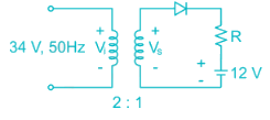
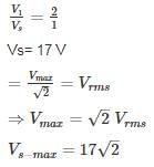
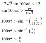
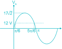
A half-wave rectifier is used to charge a 12V battery through a resistance ‘R’. The input transformer is fed with 34 AC with turns ration 2 : 1. The conduction period of the diode is
Detailed Solution: Question 1

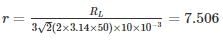
A full-wave rectifier circuit employs inductor filter at its output. If the source frequency is 50 Hz and the inductor value is 10 mH. Find the ripple factor for 100 Ω loads.
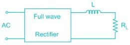
Detailed Solution: Question 2

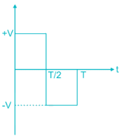
The voltage source VAB = 4 sin ωt is applied to the terminal A and B of the circuit shown In Fig. the diode is assumed to be ideal. The impedance by the circuit across the terminals A and B is ________ kΩ
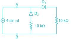
Detailed Solution: Question 3
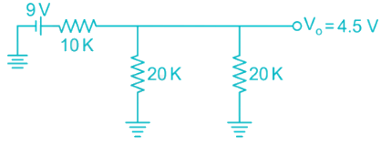
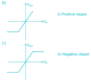
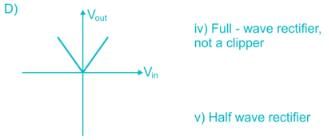
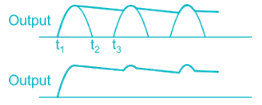
For the damping network shown below, resulting output for the applied Input will be…
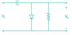
Detailed Solution: Question 4
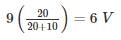
Assuming the diode to be ideal, the current I in the circuit shown is ________ mA.
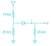
Detailed Solution: Question 5


Detailed Solution: Question 6
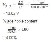
The figure shows a half wave rectifier with a load resistor of 50 Ohms. The input supply voltage is 230V(runs) at 50 Hz. A 10000 μF filter capacitor is added across the load resistor to reduce ripple. The percentage of ripple voltage at the output is ________
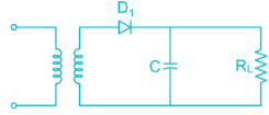
Detailed Solution: Question 7

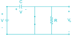
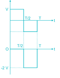
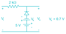
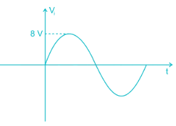
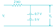
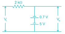
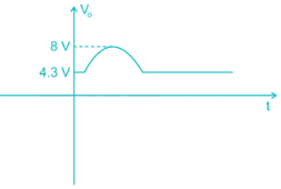
For the diode network shown below is input with voltage pulse Vi. If the knee voltage of the diode is Vk = 0.7 V then the output voltage pulse Vo is
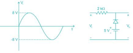
Detailed Solution: Question 8
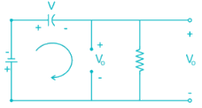
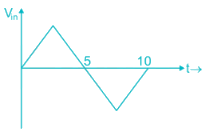
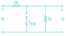
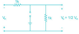
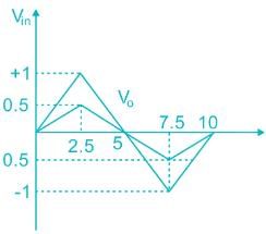
In Fig. the Input Vi is 100 Hz triangular wave having a peak to peak amplitude of 2 volts and an average value of 0 volts. Given that the diode is ideal, the average value of output Vo is ______
Detailed Solution: Question 9
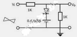
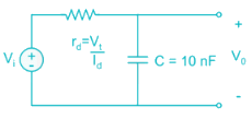
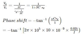
In the circuit shown I is a dC current and Vi is a sinusoidal signal with peak amplitude 10 mV and a frequency 100 kHz. The value of I that will provide a phase shift of -45° at the output is ________. μA (Assume η = 1)
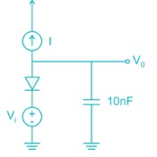
Detailed Solution: Question 10
135 videos|183 docs|71 tests |