Electrical Engineering (EE) Exam  >  Electrical Engineering (EE) Test  >  Analog and Digital Electronics  >  Analog Electronics - 2 - Electrical Engineering (EE) MCQ

Analog Electronics - 2 - Free MCQ Test with solutions for GATE EE and Digital


MCQ Practice Test & Solutions: Analog Electronics - 2 (10 Questions)

You can prepare effectively for Electrical Engineering (EE) Analog and Digital Electronics with this dedicated MCQ Practice Test (available with solutions) on the important topic of "Analog Electronics - 2". These 10 questions have been designed by the experts with the latest curriculum of Electrical Engineering (EE) 2026, to help you master the concept.

Test Highlights:

  • - Format: Multiple Choice Questions (MCQ)
  • - Duration: 30 minutes
  • - Number of Questions: 10

Sign up on EduRev for free to attempt this test and track your preparation progress.

Analog Electronics - 2 - Question 1

For the transistor circuit shown below:

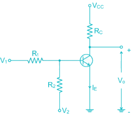
If V1 = 1V and V2 = -12V R1 = 15k and R2 = 100k R= 2.2 k Vcc = 12V Then the Region of operation of transistor is 

Detailed Solution: Question 1

V1 = 1V

V2 = -12V

R1 = 15 k

R2 = 100 k

= -0.7V

VBB­ < 0, the Base emitter Junction is reversed biased

Hence Transistor is in cut off mode

*Answer can only contain numeric values
Analog Electronics - 2 - Question 2

Calculate the value of β for the following circuit


Detailed Solution: Question 2


I= (1 + β) Iβ

3 × 10-3 = (1 + β) × 0.33 × 10⁻³

β = 89.9

Analog Electronics - 2 - Question 3

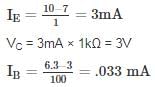
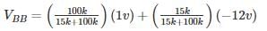
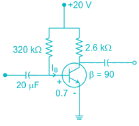
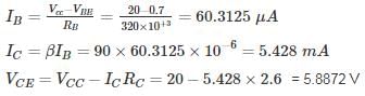
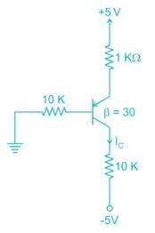
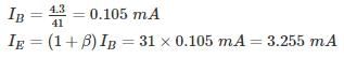
In the DC fixed bias circuit shown below the operating point is

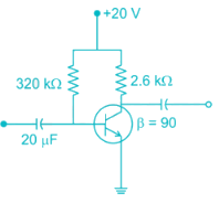
Detailed Solution: Question 3


So the operating point is (5.43 mA, 5.89 V)

Analog Electronics - 2 - Question 4

The Miller effect in the context of a Common Emitter amplifier explains

Detailed Solution: Question 4

The miller effect causes increase in the Input capacitance increase in the Input capacitance of Common – Emitter Amplifier

Upper cutoff frequency 

Therefore, there is decrease in upper-cut off frequency & Bandwidth of CE Amplifier

*Answer can only contain numeric values
Analog Electronics - 2 - Question 5

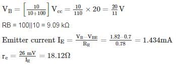
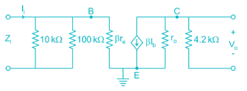
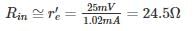
For the network shown in the figure. Find the Input independence Zi (kΩ) [Use appropriate approximation]


Detailed Solution: Question 5

DC analysis from voltage divider

Now using appropriate approximations.

Z ≅ βre = 150 × 18.2 = 2.718 kΩ

Input impedance = RB || ZB = 9.09 || 2.718 = 2.092 kΩ

Analog Electronics - 2 - Question 6

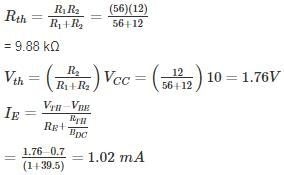
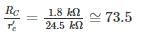
The voltage gain of the amplifier shown if β = 250 is approximately

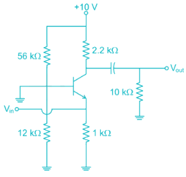
Detailed Solution: Question 6

Form DC Analysis

Since β value is large

Collector resistance = RC’ = RC ||RL

= 2.2 || 10

= 1.8 kΩ

Voltage gain = 

*Answer can only contain numeric values
Analog Electronics - 2 - Question 7


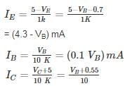
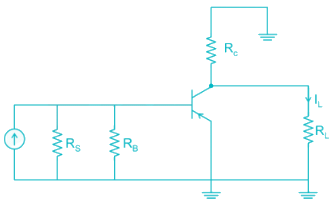
For the pnp transistor shown, the collector current IC is_______ mA.

(Assume VEB(ON) = VEB(Sat) = 0.7 V)

VEC(Sat) = 0.2 V


Detailed Solution: Question 7

Assume transistor is in active region

KVL in base emitter loop

0 + IB (10) + 0.7 + IE (1) = 5

IE = (1 + β)IB

IB (10 + 1 + 30) = 4.3

IC = βIB = 30 × 0.105 = 3.15 mA

VE = 5 – 1 (3.255)

= 1.745 V

VB = 1.745 – 0.7 = 1.045 V

VC = -5 + 10 (3.15) = 26.5 (not possible)

Transistor is not in active region it is  in saturation region

VEB = 0.7

VE = VB + 0.7

VEC = VB - VC = 0.2

VC = VB + 0.5


= (0.1VB + 0.55) mA

I= IB + IC

4.3 - VB = 0.1 VB + 0.1 VB + 0.55

VB = 3.13

Analog Electronics - 2 - Question 8

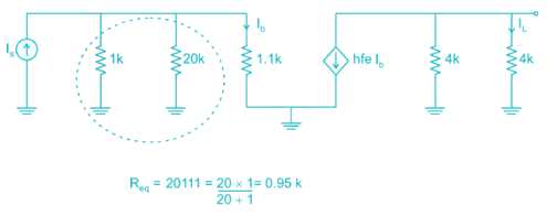
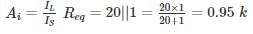
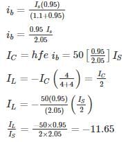
For the circuit shown in the figure if RC = 4 kΩ, RL = 4 kΩ, RB = 20 kΩ, Rs = 1 kΩ and transistor parameter are magnitude of hie = 1.1 kΩ, hfe = 50
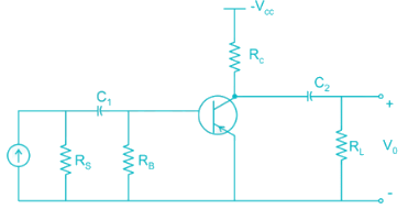
The current gain is:

Detailed Solution: Question 8

The AC equivalent circuit is:

Replacing BJT with its h-parameter model


ib using current division

iB = 0

Magnitude = |-11.65| ≈ 12

*Answer can only contain numeric values
Analog Electronics - 2 - Question 9

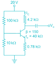
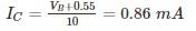
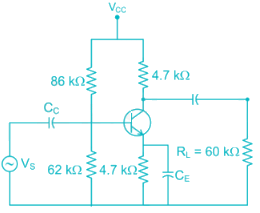
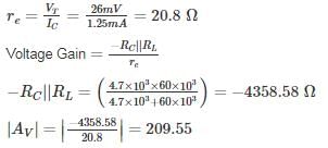
For the Common emitter configuration circuit shown below, if IC = 1.25 mA, then the magnitude of voltage gain is_______


Detailed Solution: Question 9

Given RC = 4.7 kΩ, RL = 60 kΩ, Re = 4.7 kΩ, IC = 1.5 mA

Analog Electronics - 2 - Question 10

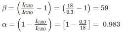
The reverse leakage current of the transistor when connected in CB Configuration is 0.3 μ A and it is 18 μA when the same transistor is connected in CE Configuration the value of α and β of the transistor for a base current of 40 mA will be respected.

Detailed Solution: Question 10


Hence α = 0.983 and β = 59

135 videos|183 docs|71 tests
Information about Analog Electronics - 2 Page
In this test you can find the Exam questions for Analog Electronics - 2 solved & explained in the simplest way possible. Besides giving Questions and answers for Analog Electronics - 2, EduRev gives you an ample number of Online tests for practice
135 videos|183 docs|71 tests
Download as PDF