Electrical Engineering (EE)  >  Analog Electronics  >  Analog Electronics - 6 Download as PDF

Analog Electronics - 6 - Electrical Engineering (EE)


Test Description

10 Questions MCQ Test Analog Electronics - Analog Electronics - 6

Analog Electronics - 6 for Electrical Engineering (EE) 2023 is part of Analog Electronics preparation. The Analog Electronics - 6 questions and answers have been prepared according to the Electrical Engineering (EE) exam syllabus.The Analog Electronics - 6 MCQs are made for Electrical Engineering (EE) 2023 Exam. Find important definitions, questions, notes, meanings, examples, exercises, MCQs and online tests for Analog Electronics - 6 below.
Solutions of Analog Electronics - 6 questions in English are available as part of our Analog Electronics for Electrical Engineering (EE) & Analog Electronics - 6 solutions in Hindi for Analog Electronics course. Download more important topics, notes, lectures and mock test series for Electrical Engineering (EE) Exam by signing up for free. Attempt Analog Electronics - 6 | 10 questions in 30 minutes | Mock test for Electrical Engineering (EE) preparation | Free important questions MCQ to study Analog Electronics for Electrical Engineering (EE) Exam | Download free PDF with solutions
1 Crore+ students have signed up on EduRev. Have you? Download the App
Analog Electronics - 6 - Question 1

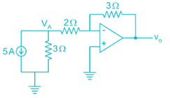
The current flowing through the 3 Ω resistor R1 is _____ A.
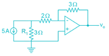
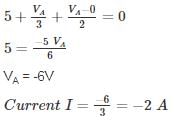
Detailed Solution for Analog Electronics - 6 - Question 1


Apply nodal at A:

Magnitude wise: 2 A

*Answer can only contain numeric values
Analog Electronics - 6 - Question 2

An op-amp has a voltage gain of 100 dB at dc and a unity gain frequency of 5 MHz. The lower 3-dB cut off frequency is _______ Hz.


Detailed Solution for Analog Electronics - 6 - Question 2

100 dB voltage gain

20 log (Gain) = 100

Gain = 105

GBW = 5 MHz

Low frequency 3-dB = 
= 50 Hz.

*Answer can only contain numeric values
Analog Electronics - 6 - Question 3

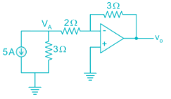
An op-amp with slew rate 1 V/μ is used in the circuit below input step voltage Vi = V sin (105t) is given, the maximum value of V such that no raise time distortion occurs at the output is _____V.
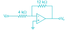

Detailed Solution for Analog Electronics - 6 - Question 3

The output Vo = -3V sin (ω0t)

For no distortion to occur

3Vω0 ≤ SR

*Answer can only contain numeric values
Analog Electronics - 6 - Question 4

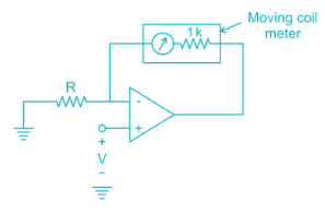
The circuit shows an analog voltmeter of very high input impedance that uses an inexpensive moving coil-meter. The voltmeter measures the voltage ‘V’ applied between the op-amp’s positive-input terminal and ground. Assuming that the moving coil produces full-scale deflection when the current passing through it is 100 μA, the value of R (in kΩ) to obtain full-scale reading at +10 V is

Detailed Solution for Analog Electronics - 6 - Question 4


VA = V (virtual ground)

Analog Electronics - 6 - Question 5

Circuit shows an op-amp circuit used for generating the square waveform.
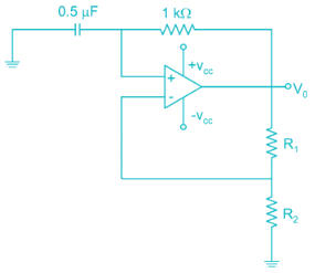
If the output frequency required in 1 kHz. then the possible values of R1­ and R2 can be respectively


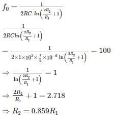
Detailed Solution for Analog Electronics - 6 - Question 5

Frequency of oscillation


If R1 = 2k

R2 = 0.859 × 2

= 1.7 k

Option 1 is correct.

*Answer can only contain numeric values
Analog Electronics - 6 - Question 6

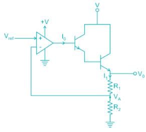
The circuit shows the series voltage regulator.
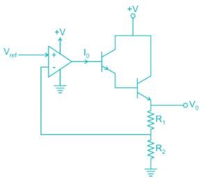
If reference voltage Vref is 2V and R1 = 3K, R2 = 1K, β = 99 for both transistors. Then the value of current I0 in micro-amperes is _____ μA.


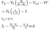
Detailed Solution for Analog Electronics - 6 - Question 6

V- = V+ = 2V


= 2 mA

I1 = (1 + β) (1 + β) I0

2 mA = 104 I0

I = 0.2 uA

Analog Electronics - 6 - Question 7

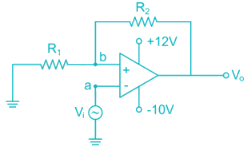
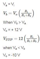
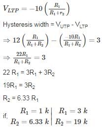
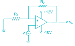
The circuit shows an – op-amp in Schmidt Trigger configuration. If the hysteresis width is 3V. Then the value of R1 and R2 is
Detailed Solution for Analog Electronics - 6 - Question 7


*Answer can only contain numeric values
Analog Electronics - 6 - Question 8

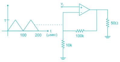
For the amplifier circuit shown, the op-amp can deliver a maximum current of 100 mA and is powered by ±15 V supply. If the input to the amplifier is a triangular waveform as shown. The peak value of the output waveform is ______.

Detailed Solution for Analog Electronics - 6 - Question 8

The circuit is non-inverting.

Amplifier:

= 11V

However the current flowing through load when V0 = 11 V is

Which is more than the current op-amp can supply.

Thus peak value is limited by the maximum current:

50 Ω ≪ 110 kΩ

All the current flows through 50 Ω resistor.

V0 = (100 mA) (50 Ω)

= 5 V

Analog Electronics - 6 - Question 9

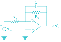
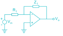
An op-amp circuit is shown in the figure. If Vin is an AC source of frequency ω.
Consider the following statements:
a) For ω Circuit is an integrator
(b) For ω circuit is an Amplifier

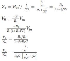
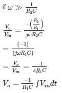
Detailed Solution for Analog Electronics - 6 - Question 9


Circuit acts like an Integrator

Circuit acts an Inverting Amplifier

The given conditions in question is opposite Hence None of a and b is correct

*Answer can only contain numeric values
Analog Electronics - 6 - Question 10

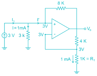
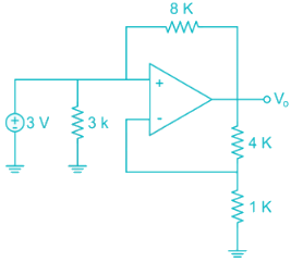
The average power delivered by the 3 V source is ________ mW.

Detailed Solution for Analog Electronics - 6 - Question 10


V- = V+ = 3 V [Virtual ground]

Current through 1 k resistor

I = 1 mA

Voltage across 1k resistor from voltage division

Voltage across  


Vo = 15 V

KVL at V+ node:

3 – I'(8) = Vo

3 – I'(8) = 15

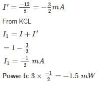
3 – 15 = I'(8)

29 videos|57 docs|108 tests
Information about Analog Electronics - 6 Page
In this test you can find the Exam questions for Analog Electronics - 6 solved & explained in the simplest way possible. Besides giving Questions and answers for Analog Electronics - 6, EduRev gives you an ample number of Online tests for practice
29 videos|57 docs|108 tests
Download as PDF
Download free EduRev App
Track your progress, build streaks, highlight & save important lessons and more!
(Scan QR code)