Electronics and Communication Engineering (ECE) Exam  >  Electronics and Communication Engineering (ECE) Tests  >  GATE ECE (Electronics) Mock Test Series 2025  >  Electronics And Communication - ECE 2021 GATE Paper (Practice Test) - Electronics and Communication Engineering (ECE) MCQ

Electronics And Communication - ECE 2021 GATE Paper (Practice Test) - Electronics and Communication Engineering (ECE) MCQ


Test Description

30 Questions MCQ Test GATE ECE (Electronics) Mock Test Series 2025 - Electronics And Communication - ECE 2021 GATE Paper (Practice Test)

Electronics And Communication - ECE 2021 GATE Paper (Practice Test) for Electronics and Communication Engineering (ECE) 2025 is part of GATE ECE (Electronics) Mock Test Series 2025 preparation. The Electronics And Communication - ECE 2021 GATE Paper (Practice Test) questions and answers have been prepared according to the Electronics and Communication Engineering (ECE) exam syllabus.The Electronics And Communication - ECE 2021 GATE Paper (Practice Test) MCQs are made for Electronics and Communication Engineering (ECE) 2025 Exam. Find important definitions, questions, notes, meanings, examples, exercises, MCQs and online tests for Electronics And Communication - ECE 2021 GATE Paper (Practice Test) below.
Solutions of Electronics And Communication - ECE 2021 GATE Paper (Practice Test) questions in English are available as part of our GATE ECE (Electronics) Mock Test Series 2025 for Electronics and Communication Engineering (ECE) & Electronics And Communication - ECE 2021 GATE Paper (Practice Test) solutions in Hindi for GATE ECE (Electronics) Mock Test Series 2025 course. Download more important topics, notes, lectures and mock test series for Electronics and Communication Engineering (ECE) Exam by signing up for free. Attempt Electronics And Communication - ECE 2021 GATE Paper (Practice Test) | 65 questions in 180 minutes | Mock test for Electronics and Communication Engineering (ECE) preparation | Free important questions MCQ to study GATE ECE (Electronics) Mock Test Series 2025 for Electronics and Communication Engineering (ECE) Exam | Download free PDF with solutions
Electronics And Communication - ECE 2021 GATE Paper (Practice Test) - Question 1

p and q are positive integers and

Detailed Solution for Electronics And Communication - ECE 2021 GATE Paper (Practice Test) - Question 1
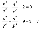
Given

Squaring on both sides, we get

Hence, the correct option is (B).

Question_Type:

Electronics And Communication - ECE 2021 GATE Paper (Practice Test) - Question 2

The current population of a city is 11,02,500. If it has been increasing at the rate of 5% per annum, what was its population 2 years ago?
Detailed Solution for Electronics And Communication - ECE 2021 GATE Paper (Practice Test) - Question 2
Given

Current population of city = 1102500

Rate of increment of population = 5% per year

Method 1 :

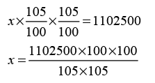
Let the population of the city 2 years ago be x . As the population has been increasing at the rate of 5% per annum, so after 2 years x becomes as,

( x × 105%) × 105% = 1102500

x = 10,00,000

Hence, the correct option is (C).

Method 2 :

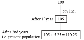
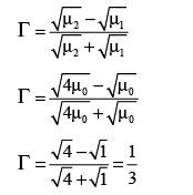
Suppose 2 years ago population of city was “100”

Hence, 2 years ago population was 100 ×10000= 1000000

Hence, the correct option is (C).

Question_Type:

Electronics And Communication - ECE 2021 GATE Paper (Practice Test) - Question 3

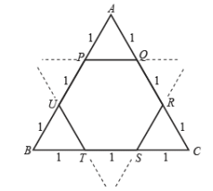
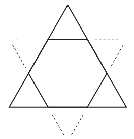
Corners are cut from an equilateral triangle to produce a regular convex hexagon as shown in the figure above.

The ratio of the area of the regular convex hexagon to the area of original equilateral triangle is

Detailed Solution for Electronics And Communication - ECE 2021 GATE Paper (Practice Test) - Question 3
Given : Equilateral triangle

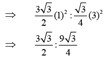
∴ Sides of Hexagon formed by an equilateral triangle to the same equilateral triangle = 1:3

∴ The ratio of the area of the regular convex Hexagon (PQRSTU) to the area of original equilateral triangle is

⇒ 2 : 3

Hence, the correct option is (A).

Question_Type:

Electronics And Communication - ECE 2021 GATE Paper (Practice Test) - Question 4

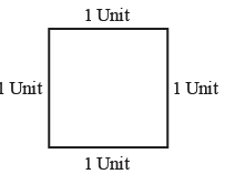
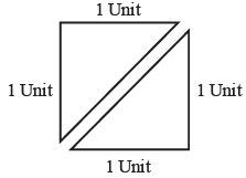
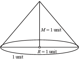
Consider a square sheet of side 1 unit. In the first step, it is cut along the main diagonal to get two triangles. In the next step, one of the cut triangles is revolved about its short edge to from solid cone. The volume of a resulting cone, in a cube units is _________.

Detailed Solution for Electronics And Communication - ECE 2021 GATE Paper (Practice Test) - Question 4
Given : Square sheet of side 1 unit.

It is cut along the main diagonal to get two triangles

One of the cut triangle is revolved about its short edge to form solid cone

Hence, the correct option is (A).

Question_Type:

Electronics And Communication - ECE 2021 GATE Paper (Practice Test) - Question 5

Nostalgia is to anticipation as _______is to _______.

Which one of the following options maintains a similar logical relation in the above sentence?
Detailed Solution for Electronics And Communication - ECE 2021 GATE Paper (Practice Test) - Question 5
Nostalgia : Recollection of a period in the past.

Anticipation : Expectation or prediction to future.

Hence, the correct option is (C).

Question_Type:

Electronics And Communication - ECE 2021 GATE Paper (Practice Test) - Question 6

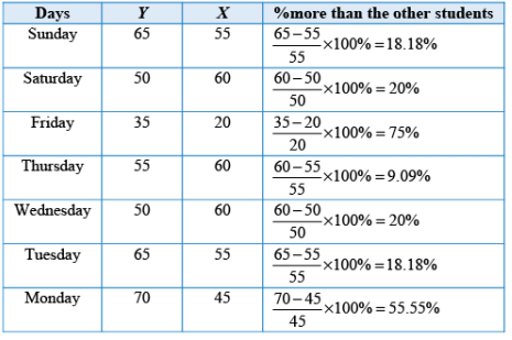
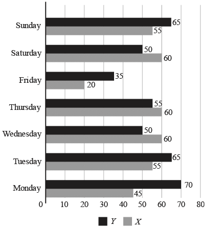
The number of minutes spent by two Students, X and Y, exercising every day in a given week are shown in the bar chart above.

The number of days in a given week in which one of the students spent a minimum of 10% more than the other student, on a given day, is
Detailed Solution for Electronics And Communication - ECE 2021 GATE Paper (Practice Test) - Question 6
According to the given data in question we can formed the table as shown below,

Except Thursday, there are total 6 days in which one of the students spent a minimum of 10% more than the other student.

Hence, the correct option is (C).

Electronics And Communication - ECE 2021 GATE Paper (Practice Test) - Question 7

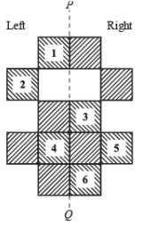
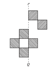
The least number of squares that must be added so that the line P-Q become the line of symmetry is _____.

Detailed Solution for Electronics And Communication - ECE 2021 GATE Paper (Practice Test) - Question 7
We have to add six square blocks to make line PQ as a line of symmetry as shown below,

Hence, the correct option is (C).

Electronics And Communication - ECE 2021 GATE Paper (Practice Test) - Question 8

Computers are ubiquitous. They are used to improve efficiency in almost all fields from agriculture to space exploration. Artificial intelligence (AI) is currently a hot topic. AI enables computer to learn, given enough training data. For humans, sitting in front of a computer for long hours can lead health issues. Which of the following can be deduced from the above passage?

(i) Nowadays computers are present in almost all places.

(ii) Computers cannot be used for solving problems in engineering.

(iii) For humans, there are positive and negative effects of using computers.

(iv) Artificial intelligence can be done without data.

Electronics And Communication - ECE 2021 GATE Paper (Practice Test) - Question 9

Given below are two statements and two conclusions.

Statement :

Statement 1 : All purple are green.

Statement 2 : All Black are green.

Conclusion :

Conclusion I : Some black are purple

Conclusion II : No black is purple

Based on the above statements and conclusions, which one of the following options is logically CORRECT?

Detailed Solution for Electronics And Communication - ECE 2021 GATE Paper (Practice Test) - Question 9
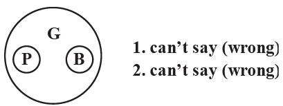
According to the statement and conclusion given in the question we can formed Venn diagram as shown below,

Both the conclusion are wrong by can’t say condition and variable of the conclusion are same. Also one conclusion is positive and another is negative. Hence they full fill the condition of “either or” case. Hence, the correct option is (C).

Electronics And Communication - ECE 2021 GATE Paper (Practice Test) - Question 10

Consider the following sentences :

(i) I woke up from sleep.

(ii) I woked up from sleep.

(iii) I was woken up from sleep.

(iv) I was wokened up from sleep.

Which of the above sentences are grammatically CORRECT?

Electronics And Communication - ECE 2021 GATE Paper (Practice Test) - Question 11

The block diagram of a feedback control system is shown in the figure,
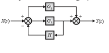
The transfer function Y(s)/X(s) of the system is

Detailed Solution for Electronics And Communication - ECE 2021 GATE Paper (Practice Test) - Question 11
Given block diagram is as shown below,

The signal flow graph is shown below,

Number of forward paths and its associate path factor is, 11

P1=G1 Δ1= 1

P2 =G2 Δ 2= 1

Number of individual loops, 11

L1 =−G1H

Determinant of SFG is,

Δ=1−(L1 ) =1−(−G1H) =1+G1 H

From the Mason’s gain formula the transfer function of this system can be given as

Hence, the correct option is (C).

Electronics And Communication - ECE 2021 GATE Paper (Practice Test) - Question 12

In the circuit shown in figure, the switch is closed at time t = 0 , while the capacitor is initially charged to – 5V [i.e. VC (0) = -5V ]
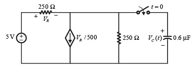
The time after which the voltage across the capacitor becomes zero is (Round off to 3 decimal places) ______ ms.


Detailed Solution for Electronics And Communication - ECE 2021 GATE Paper (Practice Test) - Question 12
Given, initial value of voltage across capacitor

VC (0− ) =− 5 V

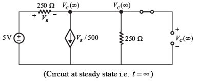
When switch is closed and circuit is in steady state (i.e. t =∞, and capacitor becomes open circuit) So circuit becomes as,

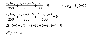
Apply KCL at node VC (∞) is,

Vc(∞) 5\3 V → Steady state voltage of capacitor 3

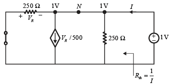
Now, for calculating time constant ( τ ), first we calculate Rth as shown below,

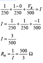
Apply KCL at node N,

Thus, time constant, て=Rth ×C

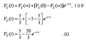
Apply transient equation for voltage across capacitor is,

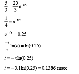
If VC(t)=0, then equations (i) becomes as,

Hence, the correct answer of t is 0.1386 msec.

Queston_Type: 4

Electronics And Communication - ECE 2021 GATE Paper (Practice Test) - Question 13

Consider the circuit with an ideal Op-Amp shown in figure,
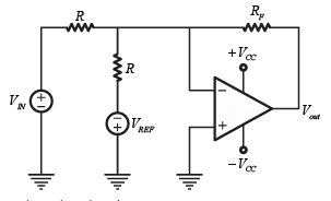
Consider the circuit with an ideal Op-Amp shown in figure,

Assuming VIN

Detailed Solution for Electronics And Communication - ECE 2021 GATE Paper (Practice Test) - Question 13
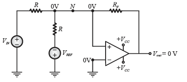
Given circuit is shown below,

According to question, |VIN| < />CC| and |VREF| < />CC|

Here, Op-Amp is ideal and -ve feedback is present so virtual ground concept is applicable.

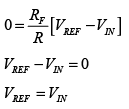
So, V+V-=0

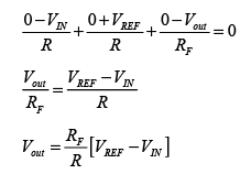
Thus applying KCL at node N,

According to question, Vout = 0

Hence, the correct answer is option (A).

*Answer can only contain numeric values
Electronics And Communication - ECE 2021 GATE Paper (Practice Test) - Question 14

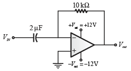
A circuit with an ideal OPAMP is shown in the figure. A pulse VIN of 20 ms duration is applied to the input. The capacitors are initially uncharged.

The output voltage Vout of this circuit at t = 0+ (in integer) is ______ V.


Detailed Solution for Electronics And Communication - ECE 2021 GATE Paper (Practice Test) - Question 14

The given circuit is shown below,

Above figure can be redrawn as

From above circuit it is clear that,

V− =VIN= + 5 V

V+= 0 V

Here, V ≠V+

It means, voltage at both terminals of op-amp are unequal and fixed so virtual ground concept is not valid here and op-amp work as a comparator.

Thus, V >V+

So, Vout =−Vsat

Vout =−12 V

Hence, the output voltage Vout of this circuit at t = 0+ is −12 V.

Question_Type: 4

Electronics And Communication - ECE 2021 GATE Paper (Practice Test) - Question 15

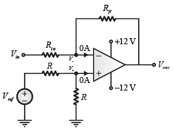
For the circuit with an ideal Op-Amp shown in the figure. VREF is fixed.
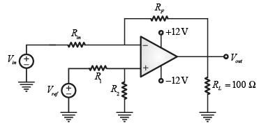
If Vout = 1 volt , for Vin = 0.1 volt and Vout = 6volt, for Vin =1volt. Where Vout is measured across RL

load connected at the output of this Op-Amp, the value of RF\Rin is.

Detailed Solution for Electronics And Communication - ECE 2021 GATE Paper (Practice Test) - Question 15
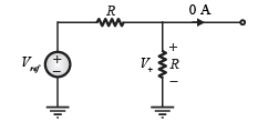
The given circuit is shown below,

Given :

(i) 1Vout =1V when Vin= 0.1 V

(ii) Vout= 6V when Vin= 1V

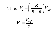
By voltage divider rule, voltage at non-inverting terminal can be found as

Here virtual ground concept is applicable because –ve feedback is present and op-amp is ideal so due to virtual ground concept,

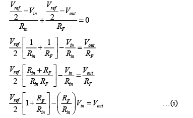
Applying KCL at V− ,

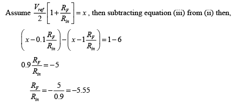
Condition 1 : If Vout = 1 V when Vin = 0.1 V then equestion (i) becomes as

Condition 2 : If Vout 6 V when Vin =1 V then equation (ii) becomes as

Note : As per the given data of question we get negative answer so none of the option is

matched.

Electronics And Communication - ECE 2021 GATE Paper (Practice Test) - Question 16

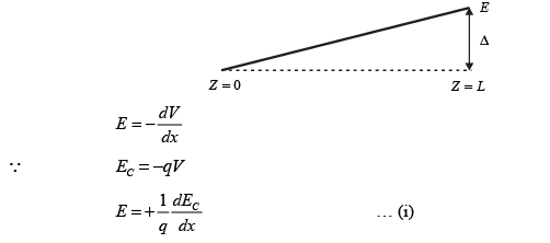
The energy band diagram of a p-type semiconductor bar of length L under equilibrium condition (i.e. the Fermi energy levels EF is constant) is shown in the figure. The valance band EV is sloped since doping is non-uniform along the bar. The difference between the energy levels of the valance band at the two edges of the bar is Δ.
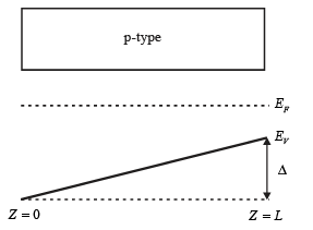
If the charge of an electron is q then the magnitude of the electric field developed inside this semiconductor bar is

Detailed Solution for Electronics And Communication - ECE 2021 GATE Paper (Practice Test) - Question 16

From questions it is clear that, change in energy level / difference in energy level of EC and EV is Δ .

Hence, equation (i) becomes as

Hence, the correct option is (A).

Electronics And Communication - ECE 2021 GATE Paper (Practice Test) - Question 17

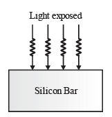
A bar of silicon is doped with boron concentration of 1016 cm-3 and assumed to be fully ionized. It is exposed to light such that electron-hole pairs are generated throughout the volume of the bar at the rate of 1020 cm-3 s-1. If the recombination lifetime is 100 μs and intrinsic carrier concentration of silicon is 1010

cm-3 and assuming 100% ionization of boron, then the approximate product of steady-state electron and hole concentration due to this light exposure is

Detailed Solution for Electronics And Communication - ECE 2021 GATE Paper (Practice Test) - Question 17
Given

Boron concentration NA = 1016 cm-3

So, NA = ppo =1016cm-3

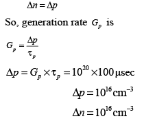
Generation Rate Gp = 1020 cm-3s-1

Recombination life time てp = 100 μ sec

Intrinsic carrier concentration n1 =1010 cm-3

Using mass action law under thermal equilibrium

So minority carrier concentration when light is not exposed is 104 cm-3 When light exposed,

So after exposing light, excess carrier concentration is

So after exposing light, under equilibrium,

1. Electrons concentration :

2. Hole concentration :

Thus, product of hole concentration and electron concentration after exposing the light is

Hence, the correct option is (D).

*Answer can only contain numeric values
Electronics And Communication - ECE 2021 GATE Paper (Practice Test) - Question 18

A silicon P-N junction is shown in the figure. The doping in the P region is 5×1016cm−3 and doping in the N region is 10 ×1016 cm−3 . The parameters given are
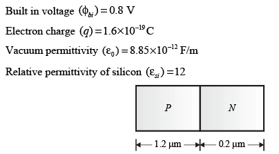
The magnitude of reverse bias voltage that would completely deplete one of the two regions (P or N) prior to the other (rounded off to one decimal place) is________ V.


Detailed Solution for Electronics And Communication - ECE 2021 GATE Paper (Practice Test) - Question 18

Given

Doping in P-region NA =5*1016 cm-3

Doping in N-region ND =1017 cm-3

Given p-n junction is shown below,

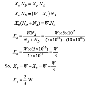
So width of depletion region, W = Xn + Xp

From charge equality concept,

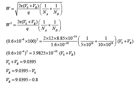
Suppose when N-is depleted completely, during reverse bias so,

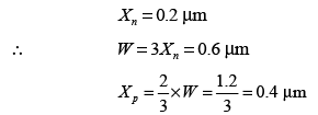
i.e. when N is depleted completely (i.e. 0.2 μm ) then and only then P side is depleted only by 0.4 μm only. Thus

So, total depletion width (W) under reverse bias is,

VR = 8.2395 V≈ 8.24 V

Thus, the magnitude of reverse bias voltage that would completely deplete N region is 8.24 V. Hence, the correct answer for VR is 8.24 V .

Question_Type: 4

Electronics And Communication - ECE 2021 GATE Paper (Practice Test) - Question 19

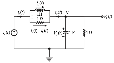
The electrical system shown in figure, converts input source current is(t) to output voltageV0(t) .
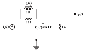
Current iL(t) in the inductor and voltage VC (t) across the capacitor are taken as the state variables, both assumed to be initially equal to zero i.e. iL (0) = 0 and VC (0) = 0 . The system is

Detailed Solution for Electronics And Communication - ECE 2021 GATE Paper (Practice Test) - Question 19
Given circuit is shown below,

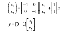
Assume, iL(t) = x1 → First state variable

VC (t) = x2 → Second state variable

is (t) = u → Input of system

and V0 (t) = y → Output of system

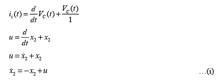
Apply KCL at node N,

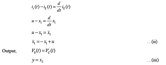
KVL in the loop between inductor and resistor,

From equation (i), (ii) and (iii), state variable modal can be written as,

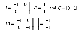
Thus matrices A, B, and C are,

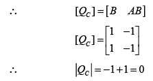
Condition of controllability,

Thus, system is uncontrollable.

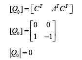
Condition of observability,

Thus, system is un-observable.

So, the system is neither controllable nor observable.

Hence, the correct option is (D).

*Answer can only contain numeric values
Electronics And Communication - ECE 2021 GATE Paper (Practice Test) - Question 20

An antenna with a directive gain of 6 dB is radiating a total power of 16 kW. The amplitude of electric field in free space at a distance of 8 km from the antenna in the direction of 6 dB gain is (Round off to 3 decimal places) ______ V/m.


Detailed Solution for Electronics And Communication - ECE 2021 GATE Paper (Practice Test) - Question 20

Given : Directive gain

Radiation power Prad =16kWrad

Distance r = 8km

Directive gain Gd (dB)=6=10 log Gd

Gd = 100.6= 3.981

So maximum electric field amplitude in free space at distance r from antenna is,

Hence, the correct answer for

Question_Type: 4

*Answer can only contain numeric values
Electronics And Communication - ECE 2021 GATE Paper (Practice Test) - Question 21

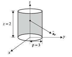
For a vector field in a cylindrical coordinate system with unit vector the net flux of leaving the closed surface of the cylinder (ρ =3, 0≤ z ≤ 2) (Round off to 2 decimal places) is ______.


Detailed Solution for Electronics And Communication - ECE 2021 GATE Paper (Practice Test) - Question 21

Cylinder (ρ =3, 0≤ z ≤ 2) is shown below,

From this given cylinder,

ρ = 3m, z= 0 to 2 m, φ = 0to 2π

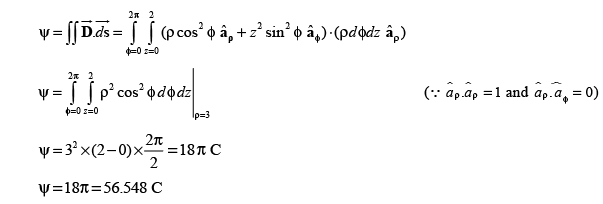
Shaded portion shows closed surface of cylinder and unit vector that is perpendicular this surface is thus, net flux leaving the closed surface of cylinder is

Hence, total flux ψ living closed surface of the given cylinder as 56.548 C.

Question_Type: 4

Electronics And Communication - ECE 2021 GATE Paper (Practice Test) - Question 22

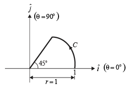
The vector function F(r) =− xiˆ +yˆj is defined over a circular are C shown in the figure,
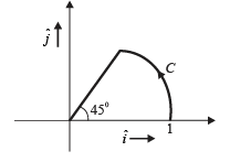
The line integral of

Detailed Solution for Electronics And Communication - ECE 2021 GATE Paper (Practice Test) - Question 22
Given : F(r) =− xiˆ +yˆj

So,

Assume, x =r cosθ, y = r sin θ

r = 1

x = cosθ and y = sinθ

Here, θ , Variation from 0 to 450 .

Put x = cosθ,y = sin θ

dx =− sin θ dθ

dy = cosθ dθ

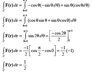
Thus equation (i) becomes as

Hence, the correct option is (A).

*Answer can only contain numeric values
Electronics And Communication - ECE 2021 GATE Paper (Practice Test) - Question 23

Consider the vector field in a rectangular coordinate system ( x, y,z) with unit vectors If the field F is irrotational (conservative), then the constant c1 (in integer) is ______.


Detailed Solution for Electronics And Communication - ECE 2021 GATE Paper (Practice Test) - Question 23

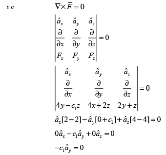
For a vector field to be irrotational its curl must be zero,

It shows because it is unit vector.

Thus, c1 = 0 then the above equation will be satisfied. Hence, the correct answer is zero.

Question_Type: 4

*Answer can only contain numeric values
Electronics And Communication - ECE 2021 GATE Paper (Practice Test) - Question 24

The refractive indices of the core and cladding of an optical fiber are 1.50 and 1.48 respectively. The critical propagation angle, which is defined as the maximum angle that the light beam makes with the axis of the optical fiber to achieve the total internal reflection (round off to two decimal places) is ______ degree.


Detailed Solution for Electronics And Communication - ECE 2021 GATE Paper (Practice Test) - Question 24

Given

Refractive index of core n1 = 1.50

Refractive index of cladding n2 = 1.48

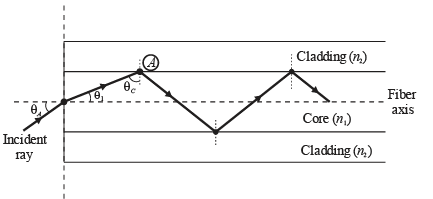
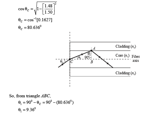
According to the definition of critical propagation angle given in statement of question, θ1, which is made with optical fiber axis and leads total internal reflection (TIR) in optical fiber cable, so we can calculate θ1 as,

Here, θA Acceptance angle

θC= Critical angle

θ1= Critical propagation angle

Where, n1 = refractive index of core = 1.5 2

n2= refractive index of cladding = 1.48

Hence, the value of critical propagation angle that leads total internal reflection in optical fiber is 9.360

Question_Type: 4

Electronics And Communication - ECE 2021 GATE Paper (Practice Test) - Question 25

Consider a rectangular coordinate system ( x, y,z) with unit vector ax, ay and az . A plane wave travelling in the region z ≥ 0 with electric field vector is incident normally on the plane at z = 0, where β is the phase constant. The region z ≥ 0 is in free space and the region z < 0="" is="" filled="" with="" a="" lossless="" medium="" (permittivity="" ε="" />0 permeability μ = 4 μ0, where ε0= 8.85 ×10⁻¹² F/m and μ= 4 π ×10-7 H/m ). The value of reflection coefficient is

Detailed Solution for Electronics And Communication - ECE 2021 GATE Paper (Practice Test) - Question 25
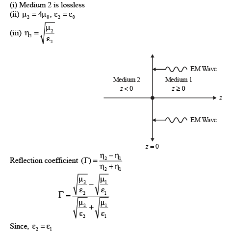
Given : Medium 1 ( z ≥ 0)

(i) Medium 1 is free space.

(ii) μ1 = μ0 , ε1= ε0

(iii) E1 = 10 cos (2×10⁸ t + βz)

(iv)

(v)

Medium 2 ( z < />

Hence, the correct option is (A).

Electronics And Communication - ECE 2021 GATE Paper (Practice Test) - Question 26

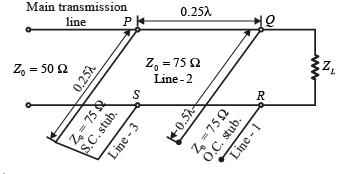
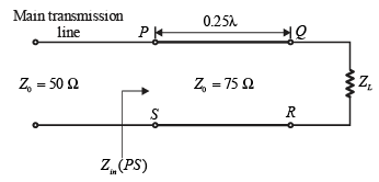
The impedance matching network shown in the figure is to match a lossless line having characteristic impedance Z0 = 50Ω with a load impedance Z L . A quarter-wave line having a characteristic impedance Z1 = 75Ω is connected to Z L . Two stubs having characteristic impedance of 75 Ω each are connected to this quarter-wave line. One is a short-circuited (S.C.) stub of length 0.25 λ connected across PS and the other one is an open-circuited (O.C.) stub of length 0.5 λ connected across QR.
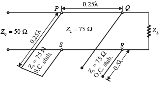
The impedance matching is achieved when the real part of ZL is

Detailed Solution for Electronics And Communication - ECE 2021 GATE Paper (Practice Test) - Question 26
Given

Lossless line characteristic impedance Z0 = 50Ω

Open circuit stub characteristic impedance ( Z1)oc = 75Ω

Short circuit stub characteristic impedance ( Z1)sc = 75Ω

Method 1 : The given arrangement of transmission line is shown below,

Input Impedance of Λ\2 long line-1,

Thus total impedance at terminal QR is,

ZQR = ZL || (Zin)Line-1= ZL || ∞= ZL

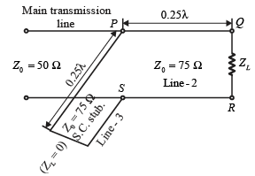
Now arrangement of Transmission Line becomes as,

Thus Input Impedance of line 2 is,

Input Impedance of Line 3 is,

Thus total impedance at terminal PS is,

ZPS = (Zin)Line-2 || (Zin)Line-3

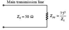
Now Transmission Line arrangement becomes as-

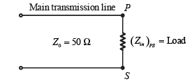
Hence ZPS work as load for main Transmission line.

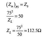
For matching of main Transmission line with load ( ZPS) ,

Hence, the correct option is (A)

Method 2 :

From given arrangement, it is clear that,

So, input impedance of both line-1 and line-3 are ∞ (i.e. open circuit) so it does not make any effect on main transmission line, so given transmission line configuration becomes as,

Thus Input Impedance at terminal PS is,

So ( Zin)PS work as load for main transmission line so arrangement of transmission line becomes as,

Hence ( Zin)PS work as load for main Transmission line so the condition, for matching the main Transmission line with load ( Zin)PS is

Hence, the correct option is (A)

*Answer can only contain numeric values
Electronics And Communication - ECE 2021 GATE Paper (Practice Test) - Question 27

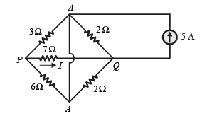
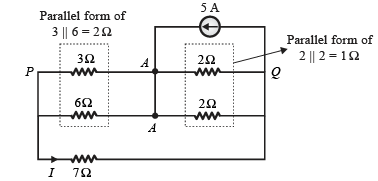
Consider the circuit shown in figure.

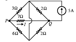
The current I flowing through the 7Ω resistor between P and Q (Round off to 1 decimal places) is _______.


Detailed Solution for Electronics And Communication - ECE 2021 GATE Paper (Practice Test) - Question 27

Given circuit is shown below,

Re-arrange the above circuit as shown below,

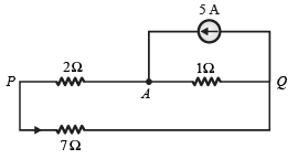
Now above circuit reduces as,

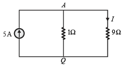
Above circuit can be re-arranged as,

Apply current divider rule

Hence, the correct answer is 0.5 A.

Question_Type: 4

Electronics And Communication - ECE 2021 GATE Paper (Practice Test) - Question 28

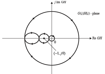
The complete Nyquist plot of the open loop transfer function G(s) H (s) of a feedback control system shown in figure,
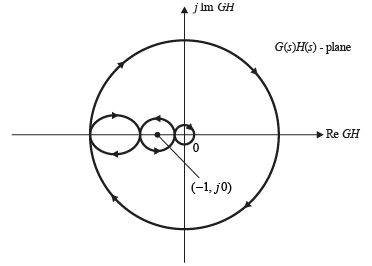
If G(s) H (s) has one zero in right half of the s-plane, the number of poles that, the closed loop system will have in right half of s-plane is

Detailed Solution for Electronics And Communication - ECE 2021 GATE Paper (Practice Test) - Question 28
Given Nyquist plot of G(s)H(s) is shown below

Case 1 :

Here, G(s)H(s) has one zero in the right half of s-plane i.e. Z = 1 .

According to principle of argument

N =P− Z (Anti clockwise direction) …(i)

Where,

N = Number of encirclements of Nyquist plot of G(s)H(s) about origin in anti-clockwise direction P = Number of poles of G(s)H(s) in right half of s-plane.

Z = Number of zeros of G(s)H(s) in right half of s-plane.

Here, N =−2 (anti clockwise direction)

Z = 1

From equation (i)

−2= P − 1

P = –1 …(ii)

So, poles cannot be negative in numbers so no more further discussion on this.

Case 2 : If we assume Nyquist contour in anti clockwise direction then according to principle of argument

N =P− Z (Clockwise direction) …(iii)

Where,

N = Number of encirclements of Nyquist plot of G(s)H(s) about origin in clockwise direction

P = Number of poles of G(s)H(s) in right half of s-plane.

Z = Number of zeros of G(s)H(s) in right half of s-plane.

Here, N = 2 (Clockwise direction)

Z = 1

From equation (iii)

2 = P−1

P = 3 …(iv)

According to Nyquist stability criteria

N =P− Z (Anti clockwise direction) …(v)

Where, N = Number of encirclements about (−1+ 0 j ) in clockwise direction

Z = Number of closed loop poles in right half of s-plane.

P = Number of open loop poles or poles of G(s)H(s) in right half of s-plane.

From given Nyquist plot number of encirclements about (−1+ 0 j ) is

N = 1−1= 0

Using equation (v)

0 = P−Z

Z = P

Z = 3

So here number of poles in right half of s-plane is 3.

Hence, the correct option is (D).

*Answer can only contain numeric values
Electronics And Communication - ECE 2021 GATE Paper (Practice Test) - Question 29

An 8-bit unipolar (all analog output values are positive) digital-to-analog converter (DAC) has a full-scale voltage range from 0 V to 7.68 V. If the digital input code is 10010110 (the leftmost bit is MSB), then the analog output voltage of the DAC (rounded off to one decimal place) is ___________V.


Detailed Solution for Electronics And Communication - ECE 2021 GATE Paper (Practice Test) - Question 29

Given : Number of bits, n = 8,

Full scale voltage,VFS= 7.68

Thus, analog output from 8 bit unipolar DAC is,

Vout = (Resolution)× (Decimal equivalent of digital input )

Hence, the analog output voltage of the 8 bit unipolar DAC is 4.517 Volt

Question_Type: 4

Electronics And Communication - ECE 2021 GATE Paper (Practice Test) - Question 30

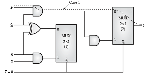
The propagation delays of the XOR gate, AND gate and multiplexer (MUX) in the circuit shown in the figure are 4 ns, 2 ns and 1 ns, respectively.
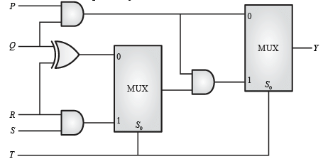
If all the inputs P, Q, R, S and T are applied simultaneously and held constant, the maximum propagation delay of the circuit is

Detailed Solution for Electronics And Communication - ECE 2021 GATE Paper (Practice Test) - Question 30
Given

Delay of XOR gate = 4ns

Delay of AND gate = 2 ns

Delay of MUX = 1ns

Case 1 :

Assuming T = 0 then selection line of MUX S0 = 0 , so that MUX input ‘0’ get enable so path followed by signal in the given circuit is shown by dotted lines as,

So total propagation delay τ2 from input to output is,

τ2= = (Propagation delay of AND gate) + (Propagation delay of MUX-1) +

(Propagation delay of AND gate) + (Propagation delay of MUX-2)

τ2= 2ns +1ns + 2ns + 1ns = 6ns

Hence MUX input '1' get enable then propagation delay of given circuit τ2= 6ns

Hence maximum delay of circuit is MAX ( τ12) = MAX ( 3ns, 6ns)= 6 ns

Hence, the correct option is (C).

View more questions
25 docs|263 tests
Information about Electronics And Communication - ECE 2021 GATE Paper (Practice Test) Page
In this test you can find the Exam questions for Electronics And Communication - ECE 2021 GATE Paper (Practice Test) solved & explained in the simplest way possible. Besides giving Questions and answers for Electronics And Communication - ECE 2021 GATE Paper (Practice Test), EduRev gives you an ample number of Online tests for practice
Download as PDF