Test: Electromagnetics - 1 - Electronics and Communication Engineering (ECE) MCQ
15 Questions MCQ Test - Test: Electromagnetics - 1

Assertion (A) : Smith chart is designed for λ/2length only.
Reason (R) : For every λ/2 length, the load impedance appears to be same as Zin.
Reason (R) : For every λ/2 length, the load impedance appears to be same as Zin.
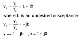
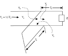
Stub matching is used to match the load to characteristic impedance. Stub should be placed such that the admittance value at that point is

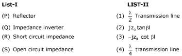
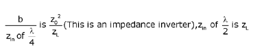
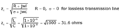
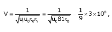
The characteristic impedance of a lossless transmission line at  is _________________ (ohms)
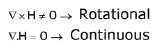
Assertion (A) : Magnetic field is continuous and always rotational.
Reason (R) : 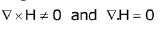
An electric wave propagating through a lossless medium  is given by
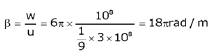
 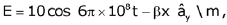 :the phase constant β is given by
Assertion (A) : Polarization is always defined in terms of electric field orientation.
Reason (R) : Magnetic field is due to induced effect of electric field so we cannot measure it directly.
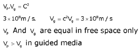
Consider a wave which is having a phase velocity of 3x10⁸m/s .Find the group ✓elocitv and the medium in which it is travelling
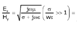
Phase difference between E and H in a high loss medium is _______________ (Degrees)
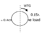
On the smith chart the location of the normalized load point is at 0.15λ, with reference to wavelength towards generator (WTG), scale operating wavelength is 4 cm. The location of first vmax from load is

Which of the following statements on a smith chart are correct?
1. Moving in clockwise direction is analogous to moving towards generator.
2. VSWR circles can be plotted on a smith chart.
3. Smith chart is the superposition of locus of VSWR and reflection coefficients.
4. To complete a distance of 0.75λ. it's enough to move 0.5λ. towards aenerator.
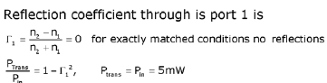
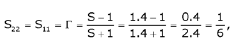
S-matrix for two port transmission line is given by  . The reflection
coefficient and the transmission power through port 1 for input power of 5 mW is
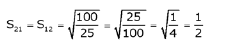
For a waveguide component whose VSWR is 1.4 when the component is terminated with a matched load. The power to the matched load is 25 mW for an input power of 100 mW. The same results are obtained when component is reversed, then the S-matrix is
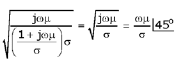
The propagation constant of a transmission line with impedance and admittance of 9 and 16 respectively is
Important Questions for Electromagnetics - 1
Electromagnetics - 1 MCQs with Answers
Online Tests for Electromagnetics - 1
|
© EduRev
|
Education Revolution
|


|


