Electronics and Communication Engineering (ECE) Exam  >  Electronics and Communication Engineering (ECE) Tests  >  GATE ECE (Electronics) Mock Test Series 2025  >  Test: Networks & Control Systems- 2 - Electronics and Communication Engineering (ECE) MCQ

Test: Networks & Control Systems- 2 - Electronics and Communication Engineering (ECE) MCQ


Test Description

20 Questions MCQ Test GATE ECE (Electronics) Mock Test Series 2025 - Test: Networks & Control Systems- 2

Test: Networks & Control Systems- 2 for Electronics and Communication Engineering (ECE) 2025 is part of GATE ECE (Electronics) Mock Test Series 2025 preparation. The Test: Networks & Control Systems- 2 questions and answers have been prepared according to the Electronics and Communication Engineering (ECE) exam syllabus.The Test: Networks & Control Systems- 2 MCQs are made for Electronics and Communication Engineering (ECE) 2025 Exam. Find important definitions, questions, notes, meanings, examples, exercises, MCQs and online tests for Test: Networks & Control Systems- 2 below.
Solutions of Test: Networks & Control Systems- 2 questions in English are available as part of our GATE ECE (Electronics) Mock Test Series 2025 for Electronics and Communication Engineering (ECE) & Test: Networks & Control Systems- 2 solutions in Hindi for GATE ECE (Electronics) Mock Test Series 2025 course. Download more important topics, notes, lectures and mock test series for Electronics and Communication Engineering (ECE) Exam by signing up for free. Attempt Test: Networks & Control Systems- 2 | 20 questions in 60 minutes | Mock test for Electronics and Communication Engineering (ECE) preparation | Free important questions MCQ to study GATE ECE (Electronics) Mock Test Series 2025 for Electronics and Communication Engineering (ECE) Exam | Download free PDF with solutions
Test: Networks & Control Systems- 2 - Question 1

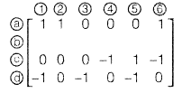
For the given circuit incidence matrix A given as
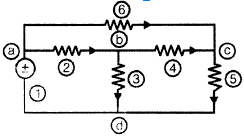
This circuit has ___________ branches of tree, ________________ links and missing row in the incidence matrix is

Detailed Solution for Test: Networks & Control Systems- 2 - Question 1

Test: Networks & Control Systems- 2 - Question 2

Two inductors L1 and L2 are connected in series. The net inductance when they additively coupled is 20 H and that of oppositely coupled Is 12 H. The mutual inductance 'M' of these two is ____________ H

Detailed Solution for Test: Networks & Control Systems- 2 - Question 2

1 Crore+ students have signed up on EduRev. Have you? Download the App
Test: Networks & Control Systems- 2 - Question 3

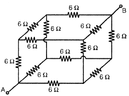
The equivalent resistance between terminals A and B is ____________
Detailed Solution for Test: Networks & Control Systems- 2 - Question 3

Test: Networks & Control Systems- 2 - Question 4

In the circuit shown in the below figure the values of E1 and E2 respectively ____________

Detailed Solution for Test: Networks & Control Systems- 2 - Question 4

Test: Networks & Control Systems- 2 - Question 5

In the figure shown below V = ?

Detailed Solution for Test: Networks & Control Systems- 2 - Question 5


Test: Networks & Control Systems- 2 - Question 6

The current flowing through the branch AB is ____________

Detailed Solution for Test: Networks & Control Systems- 2 - Question 6

Test: Networks & Control Systems- 2 - Question 7

In the circuit shown in below figure VAB and ZAB respectively _______________

Detailed Solution for Test: Networks & Control Systems- 2 - Question 7

Test: Networks & Control Systems- 2 - Question 8

The current T in the circuit shown in below figure is ______________

Detailed Solution for Test: Networks & Control Systems- 2 - Question 8

Test: Networks & Control Systems- 2 - Question 9

What is the value of Rto transfer maximum power to the load in the circuit shown in below figure is _________________Ω

Detailed Solution for Test: Networks & Control Systems- 2 - Question 9

Test: Networks & Control Systems- 2 - Question 10

Detailed Solution for Test: Networks & Control Systems- 2 - Question 10

Test: Networks & Control Systems- 2 - Question 11

The number of forward paths and number of loops of the signal flow graph shown in below figure is _____________

Detailed Solution for Test: Networks & Control Systems- 2 - Question 11

Test: Networks & Control Systems- 2 - Question 12

Consider the block diagram shown in the below figure.

Detailed Solution for Test: Networks & Control Systems- 2 - Question 12

Test: Networks & Control Systems- 2 - Question 13

A 2nd order system has a transfer function    In this system time required for the output to reach its 2nd peak for the unit step input is _____________ (in seconds).

Detailed Solution for Test: Networks & Control Systems- 2 - Question 13

Test: Networks & Control Systems- 2 - Question 14

The number of poles lies in RHS of s = 1 plane in the characteristic equation s3 + 2s2 - 5s - 6 = 0 is    

Detailed Solution for Test: Networks & Control Systems- 2 - Question 14


Test: Networks & Control Systems- 2 - Question 15

The 'root locus’ of a system is shown in the below figure. Its transfer function is _____________

Detailed Solution for Test: Networks & Control Systems- 2 - Question 15

Test: Networks & Control Systems- 2 - Question 16

A system has open-loop transfer function    Its Nyquist plot is ______________

Detailed Solution for Test: Networks & Control Systems- 2 - Question 16

Test: Networks & Control Systems- 2 - Question 17

Bode plot of a transfer function is as shown in below figure.

The corner frequency ω1 is ___________ rad/s

Detailed Solution for Test: Networks & Control Systems- 2 - Question 17

Test: Networks & Control Systems- 2 - Question 18

Match List-1, List-ll with List-Ill and select the correct answer using the codes given below the lists:

List-I
A.    lead compensator
B.    lag compensator

List-II
X.    steady state response
Y.    transient response

List-Ill

Test: Networks & Control Systems- 2 - Question 19

The figure shown in below is a signal flow graph of a system. Its transfer function  is _________________


Detailed Solution for Test: Networks & Control Systems- 2 - Question 19

Test: Networks & Control Systems- 2 - Question 20

Consider the circuit shown below:

The s.c. input admittance of the above network is __________________   

Detailed Solution for Test: Networks & Control Systems- 2 - Question 20

25 docs|263 tests
Information about Test: Networks & Control Systems- 2 Page
In this test you can find the Exam questions for Test: Networks & Control Systems- 2 solved & explained in the simplest way possible. Besides giving Questions and answers for Test: Networks & Control Systems- 2, EduRev gives you an ample number of Online tests for practice

Top Courses for Electronics and Communication Engineering (ECE)

Download as PDF

Top Courses for Electronics and Communication Engineering (ECE)