Electrical Engineering (EE) Exam  >  Electrical Engineering (EE) Test  >  GATE Mock Test Series 2027  >  Test: Number Systems, Boolean Algebra & Sequential Logic Circuits - Electrical Engineering (EE) MCQ

GATE Electrical Engineering (EE) Test: Number Systems, Boolean Algebra


MCQ Practice Test & Solutions: Test: Number Systems, Boolean Algebra & Sequential Logic Circuits (20 Questions)

You can prepare effectively for Electrical Engineering (EE) GATE Electrical Engineering (EE) Mock Test Series 2027 with this dedicated MCQ Practice Test (available with solutions) on the important topic of "Test: Number Systems, Boolean Algebra & Sequential Logic Circuits". These 20 questions have been designed by the experts with the latest curriculum of Electrical Engineering (EE) 2026, to help you master the concept.

Test Highlights:

  • - Format: Multiple Choice Questions (MCQ)
  • - Duration: 60 minutes
  • - Number of Questions: 20

Sign up on EduRev for free to attempt this test and track your preparation progress.

Test: Number Systems, Boolean Algebra & Sequential Logic Circuits - Question 1

To perform product of maxterms Boolean function must be brought into

Test: Number Systems, Boolean Algebra & Sequential Logic Circuits - Question 2

If (211)x = (152)8 , then the value of base x is

Detailed Solution: Question 2

In general, since we are comfortable dealing with Decimal system, the best way to go about under the circumstances is to convert one Number into decimal Number and then with the base x, convert another Number into Decimal Number and equate them to find the value of x.

So, (152)8 is 64*1+8*5+2, which is 106 in Decimal System.

(211)x is 2x^2+ 1*x+1 in Decimal System.

Now, we solve 2x^2+x+1 = 106

i. e. 2x^2+x-105=0

Therefore 2x^2–14x+15x-105=0

Therefore 2x(x-7)+15(x-7)=0

Therefore (x-7)(2x+15)=0

Therefore either x = 7 or x = -15/2.

Obviously x = -15/2 isnot the answer. So, x = 7 is the answer, which can be very easily verified. 2*7^2+1*7+1 = 106 which issame as (152)8.

Thus the base for 211 is 7.

Test: Number Systems, Boolean Algebra & Sequential Logic Circuits - Question 3

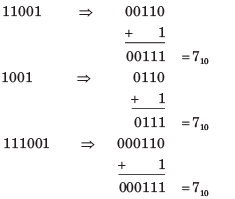
11001, 1001 and 111001 correspond to the 2’s complement representation of the following set of numbers

Detailed Solution: Question 3

All are 2’s complement of 7

Test: Number Systems, Boolean Algebra & Sequential Logic Circuits - Question 4

A signed integer has been stored in a byte using 2’s complement format. We wish to store the same integer in 16-bit word. We should copy the original byte to the less significant byte of the word and fill the more significant byte with

Detailed Solution: Question 4

See a example

Test: Number Systems, Boolean Algebra & Sequential Logic Circuits - Question 5

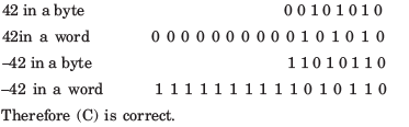
A computer has the following negative numbers stored in binary form as shown. The wrongly stored number is

Test: Number Systems, Boolean Algebra & Sequential Logic Circuits - Question 6

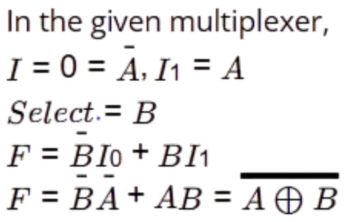
Consider the following circuit which uses a 2-to-1 multiplexer as shown in the figure below. The Boolean expression for output F in terms of A and B is

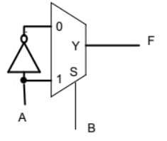
Detailed Solution: Question 6

Test: Number Systems, Boolean Algebra & Sequential Logic Circuits - Question 7

The counter shown in fig. is

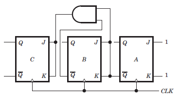
Detailed Solution: Question 7

It is a down counter because 0 state of previous FFs change the state of next FF. You may trace the following sequence, let initial state be000

Test: Number Systems, Boolean Algebra & Sequential Logic Circuits - Question 8

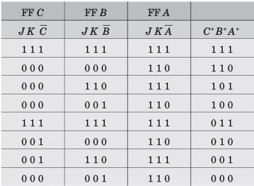
The counter shown in fig. counts from

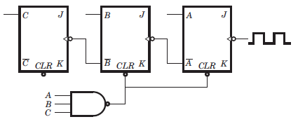
Detailed Solution: Question 8

It is a down counter because the inverted FF output drive the clock inputs. The NAND gate will clear FFs A and B when the count tries to recycle to 111. This will produce as result of 100. Thus the counting sequence will be 100, 011, 010, 001, 000, 100 etc.

Test: Number Systems, Boolean Algebra & Sequential Logic Circuits - Question 9

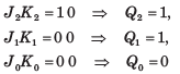
The mod-number of the asynchronous counter shown in fig. is

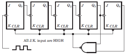
Detailed Solution: Question 9

It is a 5 bit ripple counter. At 11000 the output of NAND gate is LOW. This will clear all FF. So it is a Mod 24 counter. Note that when 11000 occur, the CLR input is activated and all FF are immediately cleared. So it is a MOD 24 counter not MOD 25.

Test: Number Systems, Boolean Algebra & Sequential Logic Circuits - Question 10

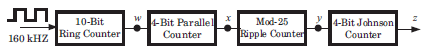
The frequency of the pulse at z in the network shown in fig. is 

Detailed Solution: Question 10

10-bit ring counter is a MOD–10, so it divides the 160 kHz input by 10. therefore, w = 16 kHz. The four-bit parallel counter is a MOD–16. Thus, the frequency at x = 1 kHz. The MOD–25 ripple counter produces a frequency at y = 40 Hz. (1 kHz/25 = 40 Hz).
The four-bit Johnson Counter is a MOD-8. This, the frequency at z = 5 Hz.

Test: Number Systems, Boolean Algebra & Sequential Logic Circuits - Question 11

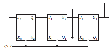
The three-stage Johnson counter as shown in fig. is clocked at a constant frequency of fc from the starting state of Q2 Q1Q0 = 101. The frequency of output Q2 Q1Q0 will be

Detailed Solution: Question 11

We see that 1 0 1 repeat after every two cycles, hence frequency will be fc/2 

Test: Number Systems, Boolean Algebra & Sequential Logic Circuits - Question 12

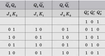
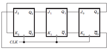
The counter shown in the fig. has initially Q2Q1Q0 = 000. The status of Q2 Q1Q after the first pulse is

Detailed Solution: Question 12

At first cycle

Test: Number Systems, Boolean Algebra & Sequential Logic Circuits - Question 13

A 4 bit ripple counter and a 4 bit synchronous counter are made by flips flops having a propagation delay of 10 ns each. If the worst case delay in the ripple counter and the synchronous counter be R and S respectively, then

Detailed Solution: Question 13

In ripple counter delay 4Td = 40 ns.

The synchronous counter are clocked simultaneously, then its worst delay will be equal to 10 ns.

Test: Number Systems, Boolean Algebra & Sequential Logic Circuits - Question 14

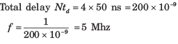
A 4 bit modulo–6 ripple counter uses JK flip-flop. If the propagation delay of each FF is 50 ns, the maximum clock frequency that can be used is equal to

Detailed Solution: Question 14

4 bit uses 4 FF

Test: Number Systems, Boolean Algebra & Sequential Logic Circuits - Question 15

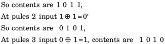
The initial contents of the 4-bit serial-in-parallel-out right-shift, register shown in fig. is 0 1 1 0. After three clock pulses are applied, the contents of the shift register will be

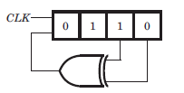
Detailed Solution: Question 15

Test: Number Systems, Boolean Algebra & Sequential Logic Circuits - Question 16

Consider the signed binary number A = 01010110 and B = 1110 1100 where B is the 1’s complement and MSB is the sign bit. In list-I operation is given, and in list-II resultant binary number is given.

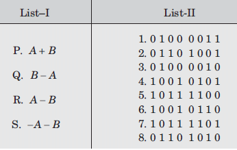
The correct match is

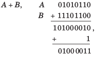
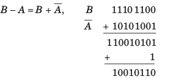
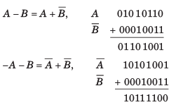
Detailed Solution: Question 16

Test: Number Systems, Boolean Algebra & Sequential Logic Circuits - Question 17

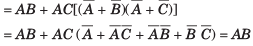
The simplified form of a logic function 

Detailed Solution: Question 17

Test: Number Systems, Boolean Algebra & Sequential Logic Circuits - Question 18

If the decimal number is a fraction then its binary equivalent is obtained by ________ the number continuously by 2.

Detailed Solution: Question 18

On multiplying the decimal number continuously by 2, the binary equivalent is obtained.

Test: Number Systems, Boolean Algebra & Sequential Logic Circuits - Question 19

The Boolean equation X = [(A + B̅) (B + C)] B can be simplified to

Detailed Solution: Question 19

X = [(A + B̅) (B + C)] B

= (AB + AC + 0 +  B̅C)B

= AB + ABC

= AB(1 + C)

= AB

Test: Number Systems, Boolean Algebra & Sequential Logic Circuits - Question 20

Detailed Solution: Question 20

26 docs|247 tests
Information about Test: Number Systems, Boolean Algebra & Sequential Logic Circuits Page
In this test you can find the Exam questions for Test: Number Systems, Boolean Algebra & Sequential Logic Circuits solved & explained in the simplest way possible. Besides giving Questions and answers for Test: Number Systems, Boolean Algebra & Sequential Logic Circuits, EduRev gives you an ample number of Online tests for practice
Download as PDF