Electronics and Communication Engineering (ECE) Exam  >  Electronics and Communication Engineering (ECE) Tests  >  GATE ECE (Electronics) Mock Test Series 2025  >  Analog Electronics - 8 - Electronics and Communication Engineering (ECE) MCQ

Analog Electronics - 8 - Electronics and Communication Engineering (ECE) MCQ


Test Description

10 Questions MCQ Test GATE ECE (Electronics) Mock Test Series 2025 - Analog Electronics - 8

Analog Electronics - 8 for Electronics and Communication Engineering (ECE) 2025 is part of GATE ECE (Electronics) Mock Test Series 2025 preparation. The Analog Electronics - 8 questions and answers have been prepared according to the Electronics and Communication Engineering (ECE) exam syllabus.The Analog Electronics - 8 MCQs are made for Electronics and Communication Engineering (ECE) 2025 Exam. Find important definitions, questions, notes, meanings, examples, exercises, MCQs and online tests for Analog Electronics - 8 below.
Solutions of Analog Electronics - 8 questions in English are available as part of our GATE ECE (Electronics) Mock Test Series 2025 for Electronics and Communication Engineering (ECE) & Analog Electronics - 8 solutions in Hindi for GATE ECE (Electronics) Mock Test Series 2025 course. Download more important topics, notes, lectures and mock test series for Electronics and Communication Engineering (ECE) Exam by signing up for free. Attempt Analog Electronics - 8 | 10 questions in 30 minutes | Mock test for Electronics and Communication Engineering (ECE) preparation | Free important questions MCQ to study GATE ECE (Electronics) Mock Test Series 2025 for Electronics and Communication Engineering (ECE) Exam | Download free PDF with solutions
Analog Electronics - 8 - Question 1

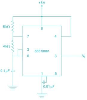
Which is the frequency of the given 555 timer?

Detailed Solution for Analog Electronics - 8 - Question 1


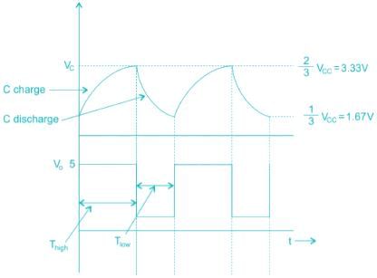
The waveforms will be like

The charge of the capacitor varies between


When capacitor is getting charged, output V0 is high

When capacitor is getting discharged, output V0 is low

The time period of o/p, T = Thigh + Tlow

In Thigh, i.e. charging time, both RA& RB are in play.


In Tlow, i.e. discharging time,

Tlow, i.e. discharging time,

Tlow = 0.693 RBC

T = Thigh + Tlow

= 0. 693(RA + 2RB)C

= 0.693 (8 + (2 × 4) × 103 × 0.1 × 10-6)

= 0.693 × 16 × 103 × 10-7

*Answer can only contain numeric values
Analog Electronics - 8 - Question 2

In the above monostable multivibrator circuit above given C = 10 nF. If the frequency of output pulse is 100 kHz the resistor value is _________ kΩ 


Detailed Solution for Analog Electronics - 8 - Question 2

The pulse duration in mono-stable multivibrator using 555 timer is T = RC In3

10-5 = 1.1 × R × 10 × 10-9

R = 909.1 Ω

≃ 0.91 kΩ 

1 Crore+ students have signed up on EduRev. Have you? Download the App
Analog Electronics - 8 - Question 3

For the 555 timer circuit, if RA = RB then

Detailed Solution for Analog Electronics - 8 - Question 3

The ON time of 555 timer is TON = RA + RB and OFF time TOFF = RB

≃ 66% > 50%

Analog Electronics - 8 - Question 4

A dc voltage of 380 V with a peak ripple voltage not exceeding 7 V is required to supply a 500 Ω load. Find out the inductance required.

Detailed Solution for Analog Electronics - 8 - Question 4

We know that the ripple factor


Where r = RMS value of AC component/DC component

RMS value of AC component = 7/1.414 = 4.95

L = 28.8 H

*Answer can only contain numeric values
Analog Electronics - 8 - Question 5

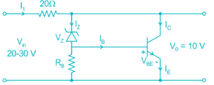
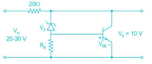
A shunt regular is shown in the figure has a regulated output voltage of 10 V. Given Vz = 9.3, VBE = 0 .7 V, β = 49. Neglecting the current through Resistor RB the ratio of maximum power dissipated in the transistor to the maximum power dissipated in the Zener diode is ________

Detailed Solution for Analog Electronics - 8 - Question 5


Maximum input current


The Base current is equal to current flowing through Zener diode

Vz = IB

→ Ic = βIB = βIZ

I1 = βIZ + Iz

1A = (49 + 1) Iz

Iz = 20 mA

∴ Power dissipated by the Zener diode Pz = VzIz

= 9.3 × 0.02 = 186 mW

Power dissipated by the Zener diode Pc = Ic × Vc

IC = 99Iz; VC = VO

⇒ PC = 0.98 × 10 = 9.8 W
∴ The ratio = 

Analog Electronics - 8 - Question 6

For the circuit shown, the value of C = 1 nF, the value of RA & R such that oscillation frequency of 100 kHz and duty cycle frequency of 75% is obtained at the output is
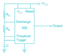
Detailed Solution for Analog Electronics - 8 - Question 6

T = 0.69 C (RA + 2RB)


4RB = 14452.75

RB = 3623

3.6 K

RA = 7.2 K

*Answer can only contain numeric values
Analog Electronics - 8 - Question 7

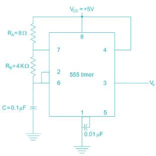
The frequency of oscillation of the astable multivibrator circuit given below is ______ 
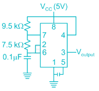

Detailed Solution for Analog Electronics - 8 - Question 7

The time period of astable multivibrator given is

T = 0.693 (RA + 2RB) C

Where RA = 9.5 kΩ RB = 7.5 kΩ

C = 0.1 μF

Frequency of oscillation is given by F = 1/T

Analog Electronics - 8 - Question 8

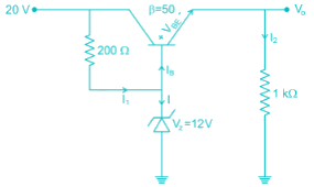
For the given circuit, what is the value of power dissipated in zener diode ?
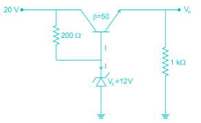
Detailed Solution for Analog Electronics - 8 - Question 8

The given circuit is of a voltage regulator, hence the output voltage will remain fixed due to zener diode.
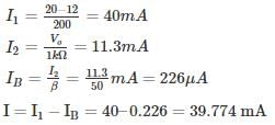
V0 = VZ – VBE = 12 − 0.7 = 11.3V
VCE = 20 – 11.3 = 8.7V


Hence power dissipated in zener diode is Pdis = V× I = 477.3 mW

*Answer can only contain numeric values
Analog Electronics - 8 - Question 9

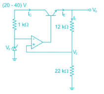
The output voltage of the voltage regulator is constant at 18.5 V. Assuming the op-amp and Zener diode are ideal, the maximum power dissipated in the transistor is ______ mw. The transistor β is very high.
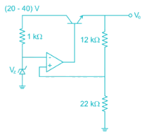

Detailed Solution for Analog Electronics - 8 - Question 9


Due to virtual short, the voltage at inverting terminal is Vz

Then the current 

≃ 0.545 mA

Since op-amp is ideal no current is drawn by it,

⇒ IC ≃ IE = I1

VCE = (20 ~ 40) V – 18.5 V

VCEmax = 21.5 V

Power dissipated (maximum) = 21.5 × 0.545 mA

≃ 11.72 mW

*Answer can only contain numeric values
Analog Electronics - 8 - Question 10

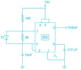
For the timer circuit shown below the frequency of oscillation is __________ kHz.

Detailed Solution for Analog Electronics - 8 - Question 10

In the given circuit R= 10 kΩ RB = 5 kΩ C = 1 nF

The frequency of oscillation

Normally the duration of 'high' of pulse is TH = C(RA + RB)ln 2, but the diode bypasses the lower resistance RB. And the capacitor is charged only through RA.

Hence TH is = 0.69RAC and TL = 0.69RBC

25 docs|263 tests
Information about Analog Electronics - 8 Page
In this test you can find the Exam questions for Analog Electronics - 8 solved & explained in the simplest way possible. Besides giving Questions and answers for Analog Electronics - 8, EduRev gives you an ample number of Online tests for practice

Top Courses for Electronics and Communication Engineering (ECE)

Download as PDF

Top Courses for Electronics and Communication Engineering (ECE)