Electrical Engineering (EE) Exam  >  Electrical Engineering (EE) Test  >  GATE Mock Test Series 2027  >  Test: Auto-Transformer - Electrical Engineering (EE) MCQ

Test: Auto-Transformer - Electrical Engineering (EE) MCQ


Test Description

10 Questions MCQ Test GATE Electrical Engineering (EE) Mock Test Series 2027 - Test: Auto-Transformer

Test: Auto-Transformer for Electrical Engineering (EE) 2026 is part of GATE Electrical Engineering (EE) Mock Test Series 2027 preparation. The Test: Auto-Transformer questions and answers have been prepared according to the Electrical Engineering (EE) exam syllabus.The Test: Auto-Transformer MCQs are made for Electrical Engineering (EE) 2026 Exam. Find important definitions, questions, notes, meanings, examples, exercises, MCQs and online tests for Test: Auto-Transformer below.
Solutions of Test: Auto-Transformer questions in English are available as part of our GATE Electrical Engineering (EE) Mock Test Series 2027 for Electrical Engineering (EE) & Test: Auto-Transformer solutions in Hindi for GATE Electrical Engineering (EE) Mock Test Series 2027 course. Download more important topics, notes, lectures and mock test series for Electrical Engineering (EE) Exam by signing up for free. Attempt Test: Auto-Transformer | 10 questions in 10 minutes | Mock test for Electrical Engineering (EE) preparation | Free important questions MCQ to study GATE Electrical Engineering (EE) Mock Test Series 2027 for Electrical Engineering (EE) Exam | Download free PDF with solutions
Test: Auto-Transformer - Question 1

While comparing potential transformer to an auto transformer, a potential transformer transfers power ________

Detailed Solution for Test: Auto-Transformer - Question 1

A potential transformer is a device that transfers electrical power through inductive coupling. This means it uses electromagnetic fields to transfer energy from one circuit to another without direct electrical connection.

A potential transformer is primarily used for measurement and protection in power systems.
It provides isolation between the high-voltage circuit and the measuring instruments.
Power transfer occurs inductively rather than conductively.

In contrast, an auto transformer can transfer power both conductively and inductively, as it has common windings between the input and output.

Test: Auto-Transformer - Question 2

The statements which support the points that auto transformers are disadvantageous as compared to 2-winding transformer
I. Weight of conductor reduces
II. Direct electrical contacts
III. Leakage reactance reduces
IV. Higher short-circuit current

Detailed Solution for Test: Auto-Transformer - Question 2

 Direct electrical contacts is a disadvantage to the auto transformer.
Short circuit current of the auto transformer is higher than the corresponding 2-winding transformer.

Test: Auto-Transformer - Question 3

I. KVA rating : 1/(1-k) II. Losses : (1-k) III. Impedance drop = 1/(1-k) Which of the above are correct for an auto transformer when compared to an identical-rating two-winding transformer?

Detailed Solution for Test: Auto-Transformer - Question 3

Option A is correct.

Assume k = V2/V1 where V1 is the higher terminal voltage and V2 the lower (tap) terminal voltage. Let the load apparent power be S = V2·I2.

The magnetically transformed (electromagnetic) VA in the autotransformer (the portion actually linked by flux) is S_m = (V1 - V2)·I2 = V1(1 - k)·I2.

Eliminating I2 between S and S_m gives S = (k/(1 - k))·S_m. This shows that for the same magnetically transformed VA rating (S_m) the autotransformer can deliver a larger terminal VA. Rearranging, the delivered kVA of the autotransformer is larger than the two-winding value by the factor 1/(1 - k); hence statement I is correct.

Copper loss in the portion that carries the transformed flux is proportional to the square of current in that portion. Because the autotransformer reduces the magnetically transformed VA (so that for the same delivered S the transformed portion carries smaller share of the VA), the copper loss of the autotransformer (for the same delivered output) is reduced roughly in proportion to the conducting/transforming portion. The standard comparison gives copper-loss (and active portion of winding loss that is avoided) reduced by the factor (1 - k) compared with the equivalent two-winding transformer; therefore statement II is correct.

The equivalent series impedance referred to the same terminals is reduced (not increased) for an autotransformer compared with the two-winding transformer because a portion of the voltage is supplied conductively. Thus the impedance drop seen at the terminals is smaller by approximately the factor (1 - k), so statement III, which gives 1/(1 - k), is incorrect.

Therefore statements I and II are correct and statement III is incorrect. Final answer: I and II (Option A).

Test: Auto-Transformer - Question 4

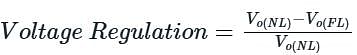
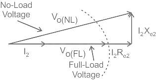
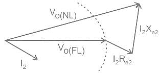
The voltage regulation of a transformer at full-load 0.8 p.f leading is -2%. Its voltage regulation at full load 0.8 p.f lagging

Detailed Solution for Test: Auto-Transformer - Question 4

The leading p.f. has negative v.r. and lagging p.f. has major portion of positive voltage regulation.

Test: Auto-Transformer - Question 5

The voltage regulation of a transformer is not dependent on its

Detailed Solution for Test: Auto-Transformer - Question 5

Voltage regulation is independent of the size of the transformer.

Test: Auto-Transformer - Question 6

Three transformers having identical dimensions but with core of iron, aluminium and wood are wound with same number of turns and have same supply.Then choose the order for hysteresis losses.

Detailed Solution for Test: Auto-Transformer - Question 6

Hysteresis losses occur maximum in the ferromagnetic material.

Test: Auto-Transformer - Question 7

Maximum efficiency of a transformer for a constant load current , occurs at

Detailed Solution for Test: Auto-Transformer - Question 7

Efficiency = KVA*p.f/(KVA*p.f + Losses); So the efficiency is maximum at unity power factor.

Test: Auto-Transformer - Question 8

A 1-phase tranformer has a leakage impedance of 1+ j4 Ω for primary and 3+ j11 Ω for secondary windings. This transformer has

Detailed Solution for Test: Auto-Transformer - Question 8

The side which has lower impedance will have lower number of turns and so the low voltage side.

Test: Auto-Transformer - Question 9

If a transformer is at no load , then it will act like

Detailed Solution for Test: Auto-Transformer - Question 9

Transformer is nothing but the arranged windings which are magnetically coupled. The windings will inductive predominantly with very low resistance.

Test: Auto-Transformer - Question 10

Which of the following power factor gives positive voltage regulation in transformer?

Detailed Solution for Test: Auto-Transformer - Question 10

Concept:

The percentage change in output voltage from no-load to full-load is termed the voltage regulation of the transformer.

Voltage Regulation of Transformer at Unity Power Factor

The phasor diagram of this case is given

It shows a phasor diagram for the case of a resistive load (unity power factor) on the transformer 
Since the current I2 is in phase with the secondary voltage Vo (FL), the voltage drop across Re2 is also in phase with Vo (FL).
The drop across the leakage reactance Xe2 leads the secondary voltage V(FL) by 90o
The referred value of primary voltage Vo (NL) is beyond the arc, so it is bigger than the secondary voltage Vo (FL), which means the voltage regulation calculated is positive.

Voltage Regulation of Transformer at Lagging Power Factor

The phasor diagram for this case is 

It shows a phasor diagram for the case of an inductive load (lagging power factor) on the transformer (i.e., the load current lags the secondary voltage by 90o). The referred value of primary voltage Vo (NL) is beyond the arc,
So it is bigger than the secondary voltage Vo (FL), which means the voltage regulation calculated is positive for an inductive case.
For any current that lags the secondary voltage by 0 to 90o, the voltage regulation will be positive.

Voltage Regulation of Transformer at Leading Power Factor

The phasor diagram for this case is 

It shows a phasor diagram for the case of a capacitive load (leading power factor) on the transformer i.e., the load current leads the secondary voltage by 90o.
As a result, the referred value of primary voltage Vo (NL) is actually smaller than the secondary voltage Vo (FL), which means the voltage regulation calculated is negative for a capacitive case.
26 docs|247 tests
Information about Test: Auto-Transformer Page
In this test you can find the Exam questions for Test: Auto-Transformer solved & explained in the simplest way possible. Besides giving Questions and answers for Test: Auto-Transformer, EduRev gives you an ample number of Online tests for practice
Download as PDF