Test: Frequency Response - Electronics and Communication Engineering (ECE) MCQ
20 Questions MCQ Test GATE ECE (Electronics) Mock Test Series 2025 - Test: Frequency Response

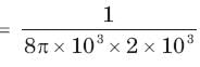
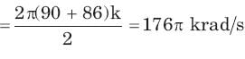
A parallel resonant circuit has a resistance of 2 kΩ and half power frequencies of 86 kHz and 90 kHz.1. The value of capacitor is
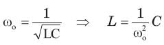
A parallel resonant circuit has a resistance of 2 kΩ and half power frequencies of 86 kHz and 90 kHz.The value of inductor is
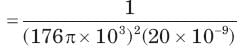 = 0.16 mH
| 1 Crore+ students have signed up on EduRev. Have you? Download the App |
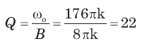
A parallel resonant circuit has a resistance of 2 kΩ and half power frequencies of 86 kHz and 90 kHz.The quality factor is
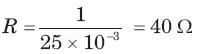
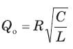
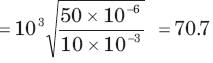
A parallel resonant circuit has a midband admittance of 25 x 10-3 S, quality factor of 80 and a resonant frequency of 200 krad/s.The value of R is
A parallel resonant circuit has a midband admittance of 25 x 10-3 S, quality factor of 80 and a resonant frequency of 200 krad/s.The value of C is

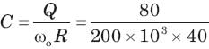 = 10 μF
A parallel RLC circuit has R =1 kΩ and C = 1 μF. Thequality factor at resonance is 200. The value of inductor is
A parallel circuit has R =1 k , C = 50 μF and L = 10mH. The quality factor at resonance is
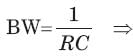
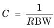
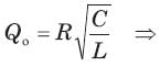
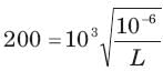
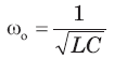
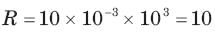
A series resonant circuit has an inductor L = 10 mH.The resonant frequency ωo = 106 rad/s and bandwidth is BW = 103 rad/s. The value of R and C will be
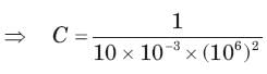 = 100pF
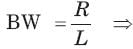
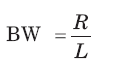
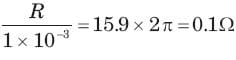
A series resonant circuit has L = 1 mH and C = 10μF. The required R for the BW 15.9 Hz is
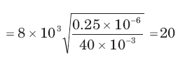
For the RLC parallel resonant circuit when R = 8 kΩ , L = 40 mH and C = 0.25 μF, the quality factor Q is


 ⇒
⇒

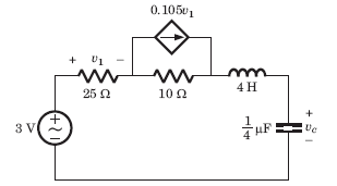
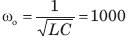
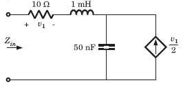
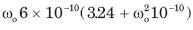
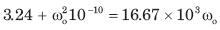
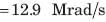
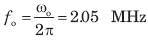
For the circuit shown in fig. the resonant frequency fo is


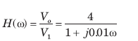
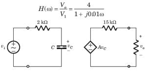
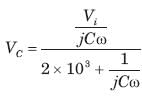
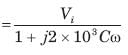
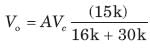
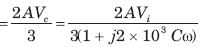
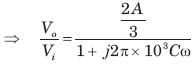

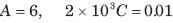

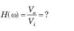
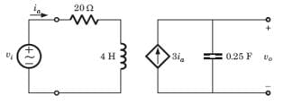
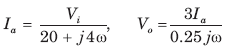
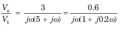
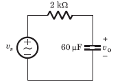
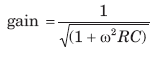
The value of input frequency is required to cause again equal to 1.5. The value is

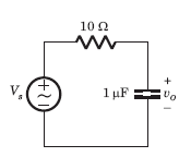
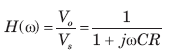
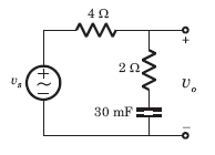
In the circuit of fig. phase shift equal to -450 is required at frequency ω =20 rad/s . The value of R is
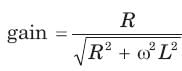
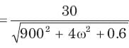
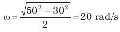
For the circuit of fig., Vs is the source voltage and the response is the resistance voltage Vo, R = 30Ω and L = 2H. Suppose the input frequency is adjusted until the gain is equal to 0.6. The value of the frequency is
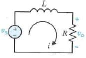
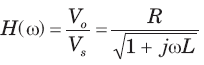
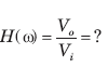
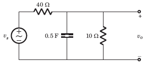
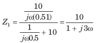
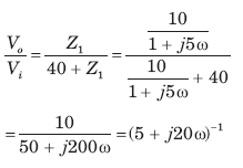
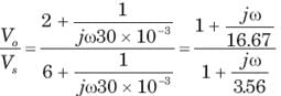
Bode diagram of the network function Vo /Vs for the circuit of fig. is
|
25 docs|263 tests
|
|
25 docs|263 tests
|
Top Courses for Electronics and Communication Engineering (ECE)


Important Questions for Frequency Response
Frequency Response MCQs with Answers
Online Tests for Frequency Response GATE ECE (Electronics) Mock Test Series 2025
|
© EduRev
|
Education Revolution
|


|


