Electrical Engineering (EE) Exam  >  Electrical Engineering (EE) Tests  >  GATE Electrical Engineering (EE) Mock Test Series 2025  >  Test: Power Electronics - 1 - Electrical Engineering (EE) MCQ

Test: Power Electronics - 1 - Electrical Engineering (EE) MCQ


Test Description

10 Questions MCQ Test GATE Electrical Engineering (EE) Mock Test Series 2025 - Test: Power Electronics - 1

Test: Power Electronics - 1 for Electrical Engineering (EE) 2024 is part of GATE Electrical Engineering (EE) Mock Test Series 2025 preparation. The Test: Power Electronics - 1 questions and answers have been prepared according to the Electrical Engineering (EE) exam syllabus.The Test: Power Electronics - 1 MCQs are made for Electrical Engineering (EE) 2024 Exam. Find important definitions, questions, notes, meanings, examples, exercises, MCQs and online tests for Test: Power Electronics - 1 below.
Solutions of Test: Power Electronics - 1 questions in English are available as part of our GATE Electrical Engineering (EE) Mock Test Series 2025 for Electrical Engineering (EE) & Test: Power Electronics - 1 solutions in Hindi for GATE Electrical Engineering (EE) Mock Test Series 2025 course. Download more important topics, notes, lectures and mock test series for Electrical Engineering (EE) Exam by signing up for free. Attempt Test: Power Electronics - 1 | 10 questions in 30 minutes | Mock test for Electrical Engineering (EE) preparation | Free important questions MCQ to study GATE Electrical Engineering (EE) Mock Test Series 2025 for Electrical Engineering (EE) Exam | Download free PDF with solutions
Test: Power Electronics - 1 - Question 1

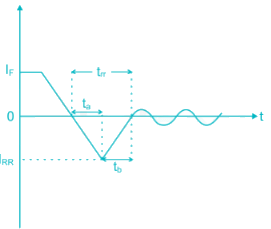
A power diode is in the forward conduction mode and the forward current is now decreased. The reverse recovery time of the diode is trr and the rate of fall of the diode current is di/dt. What is the stored charge?

Detailed Solution for Test: Power Electronics - 1 - Question 1

The reverse recovery characteristic of a power diode is shown below. reverse recovery time trr composed of ta and tb


ta is the time between zero crossings and peak reverse current IRR and tb is measured from reverse peak IRR value to 0.25 IRR.

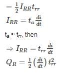
If the characteristics are assumed to be triangular (i.e. abrupt recovery) then from the figure charge stored is

QRR = area of the triangle


Test: Power Electronics - 1 - Question 2

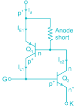
A G.T.O with anode fingers has

Detailed Solution for Test: Power Electronics - 1 - Question 2


The short circuiting fingers, also called anode-shorts, leads to short-circuit of the emitter p+(Anode A) with base n of Q1 transistor as shown in Fig. For anode or emitter current Ia, effective emitter current IE1 is reduced because of anode short. This further decreases collector current IC1. Therefore, effective current gain α1 of Q1, now given by IC1/Ia gets reduced. So by anode-short structure, α1 is reduced but α2 remains unchanged as desired.

Anode-short, however, reduces reverse voltage blocking capability. With reverse biased GTO, junction that blocks reverse voltage is J3 only. Junction J1 blocks no voltage because of n+fingers in between p+ anode. As J3 junction has large doped layers p+, n+ on its two sides, J3 has lower breakdown voltage, of the order of about 20 to 30 V.

1 Crore+ students have signed up on EduRev. Have you? Download the App
Test: Power Electronics - 1 - Question 3

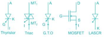
Four power semiconductor device are shown in the figure along with relevant terminals. The device that can carry dc current continuously in the Direction shown when gated appropriately is (are)
Detailed Solution for Test: Power Electronics - 1 - Question 3
  • Thyristor is unidirectional and bipolar switch. It carry current Anode to cathod and block the current cathode to anode
  • Triac conduct in both the direction A triac is thus a bidirectional thyristor with three terminal
  • GTO is just like SR it is unidirectional and bipolar It conducts only Anode to cathode
  • MOSFET is bidirectional but unipolar device
  • LASER is conduct only one direction.
*Answer can only contain numeric values
Test: Power Electronics - 1 - Question 4

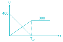
In power transistor, during turn on process voltage and current change linearly from 400 V and 0 V and 0 A to 300 A respectively in 3 μS. the energy loss during turn on process in given by _____Joule (up to 2 decimal places)


Detailed Solution for Test: Power Electronics - 1 - Question 4

Concept:

Change in V and L are shown below

Energy loss during turn on process =
Calculations:

= 20 × 103 × 3 × 10-6

= 0.06 J

*Answer can only contain numeric values
Test: Power Electronics - 1 - Question 5

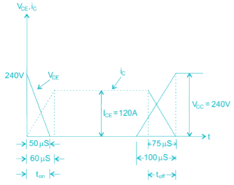
A power transistor has its switching waveforms as shown in fig. If the average power loss in the transistor is limited to 470 W, find the switching frequency at which this transistor can be operated – (in kHz)

Detailed Solution for Test: Power Electronics - 1 - Question 5

Energy loss during turn – on

= 0.2 watt – sec.

Energy loss during turn – off

= 0.27 watt – sec

Total energy loss in one cycle = 0.2 + 0.27

= 0.47 watt – sec.

Average power loss in transistor

= switching frequency × energy loss in one cycle

⇒ Switching frequency =470/0.47

= 1000 Hz.

Test: Power Electronics - 1 - Question 6

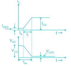
For a power transistor typical switching waveform shown in Fig. the various parameter of the transistor circuit are as under: Vcc = 220V, VCES = 2V, Ics = 80 A, td = 0.4 μs tr = 1 μs f = 5 kHz and ICEO = 2mA. Determine Average Power loss during turn-on time.
Detailed Solution for Test: Power Electronics - 1 - Question 6

Concept:

Average power loss during delay time with o < t < td

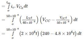
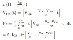
Average power loss during rise time is

Calculations:

Pd = 5 × 103 × 2 × 10−3 × 220 × 4 × 10−6 = 88mW

Pr = 5 × 103 × 80 × 1 × 10−6 = 14.933W
Total power loss during turn on time = 14.933 + 0.00088 = 14.9339 W

Test: Power Electronics - 1 - Question 7

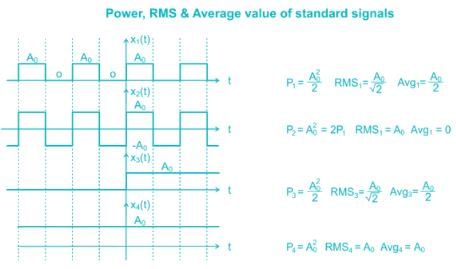
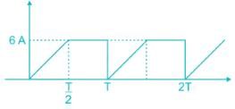
In a power electronics circuit, MOSFET is using as the switch, MOSFET with an ON state resistance 50 mΩ has with the following switching characteristics. The power losses associated with MOSFET are
Detailed Solution for Test: Power Electronics - 1 - Question 7

Concept:


Calculations:

P = Irms2 × 50 × 10-3 = 24 × 50 × 10-3 = 1.2 W

*Answer can only contain numeric values
Test: Power Electronics - 1 - Question 8

Find the time required (in hour) to deliver a charge of 400 Ah through a single phase half-wave diode Rectifier with an output current 200 A rms and with sinusoidal input voltage. Assume diode conduction over a half-cycle


Detailed Solution for Test: Power Electronics - 1 - Question 8

Correct Answer :- 3.14

Explanation : For half-wave diode rectifier

R.M.S value of the output voltage

Vor = [1/2π ∫(0 to π) Vm2 sin2ωt d(ωt)]1/2

= Vm/(2π)1/2[∫(0 to π)(1-cos2ωt)/2 d(ωt)]1/2

= Vm/2

Ior = Vm/2R

Average value of load current I0 = Vm/πR

Ior = Vm/2E

Io × time = 400 Ah

∴ Time required = (400*π)/400

= 3.14 hrs

Test: Power Electronics - 1 - Question 9

A gate turn off (GTO) thyristor has capacity to

Detailed Solution for Test: Power Electronics - 1 - Question 9


  • The Gate turn off thyristor (GTO) is a four-layer PNPN power semiconductor switching device that can be turned on by a short pulse of gate current and
  • can be turned off by a reverse gate pulse.
  • The magnitude of latching, holding currents is more. The latching current of the GTO is several times more as compared to conventional thyristors of the
  • same rating.
  • On state voltage drop and the associated loss is more.
  • Due to the multi-cathode structure of GTO, triggering gate current is higher than that required for normal SCR.
  • Gate drive circuit losses are more. Its reverse voltage blocking capability is less than the forward voltage blocking capability.
  • GTO has the capability of being turned off by a negative gate – current pulse
*Answer can only contain numeric values
Test: Power Electronics - 1 - Question 10

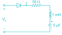
For the circuit shown in Fig R = 10 Ω L = 1 mH C = 5 μF and VS = 230 V. the circuit is initially relaxed determine conduction time of diode _________ μs

Detailed Solution for Test: Power Electronics - 1 - Question 10

Concept:

Apply KVL

The roots of the characteristic equation are

Ringing Frequency in rod/sec = ω
 

Calculations:

Conduction time of diode = π/ωr

Conduction time = 

25 docs|247 tests
Information about Test: Power Electronics - 1 Page
In this test you can find the Exam questions for Test: Power Electronics - 1 solved & explained in the simplest way possible. Besides giving Questions and answers for Test: Power Electronics - 1, EduRev gives you an ample number of Online tests for practice

Up next

Download as PDF

Up next