Electrical Engineering (EE) Exam  >  Electrical Engineering (EE) Tests  >  GATE Electrical Engineering (EE) Mock Test Series 2025  >  Test: Power Electronics - Electrical Engineering (EE) MCQ

Test: Power Electronics - Electrical Engineering (EE) MCQ


Test Description

25 Questions MCQ Test GATE Electrical Engineering (EE) Mock Test Series 2025 - Test: Power Electronics

Test: Power Electronics for Electrical Engineering (EE) 2024 is part of GATE Electrical Engineering (EE) Mock Test Series 2025 preparation. The Test: Power Electronics questions and answers have been prepared according to the Electrical Engineering (EE) exam syllabus.The Test: Power Electronics MCQs are made for Electrical Engineering (EE) 2024 Exam. Find important definitions, questions, notes, meanings, examples, exercises, MCQs and online tests for Test: Power Electronics below.
Solutions of Test: Power Electronics questions in English are available as part of our GATE Electrical Engineering (EE) Mock Test Series 2025 for Electrical Engineering (EE) & Test: Power Electronics solutions in Hindi for GATE Electrical Engineering (EE) Mock Test Series 2025 course. Download more important topics, notes, lectures and mock test series for Electrical Engineering (EE) Exam by signing up for free. Attempt Test: Power Electronics | 25 questions in 75 minutes | Mock test for Electrical Engineering (EE) preparation | Free important questions MCQ to study GATE Electrical Engineering (EE) Mock Test Series 2025 for Electrical Engineering (EE) Exam | Download free PDF with solutions
Test: Power Electronics - Question 1

In the circuit shown, the capacitor has initial voltage V0 with upper plate positive the conduction time for the Diode D
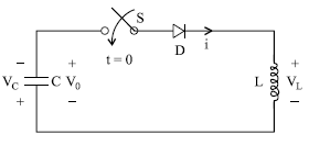
Detailed Solution for Test: Power Electronics - Question 1


Test: Power Electronics - Question 2

In the above question, the steady state voltage across the capacitor

Detailed Solution for Test: Power Electronics - Question 2

1 Crore+ students have signed up on EduRev. Have you? Download the App
Test: Power Electronics - Question 3

A single phase transformer with secondary voltage 230V, 50Hz, delivers power to load R = 10 through a half wave controlled rectifier circuit. For a firing angle delay at 60 degrees, the form factor will be

Detailed Solution for Test: Power Electronics - Question 3

Test: Power Electronics - Question 4

In the above question, Voltage ripple Factor will be

Detailed Solution for Test: Power Electronics - Question 4

Test: Power Electronics - Question 5

The circuit shown in figure is initially relaxed. If the thyristor is turn on at t = 0, what is the conduction time of thyristor

Detailed Solution for Test: Power Electronics - Question 5

Apply KVL,

Test: Power Electronics - Question 6

In a thyristor, the holding current IH is

Detailed Solution for Test: Power Electronics - Question 6

Latching current is two to three
time the holding current

Test: Power Electronics - Question 7

In the circuit shown below the thyristor is fired at an angle π/4 in every positive half cycle of the input
ac voltage the average power across the load will be

Detailed Solution for Test: Power Electronics - Question 7

Test: Power Electronics - Question 8

A half controlled bridge converter is operating from an r.m.s input voltage of 120V. Neglecting the voltage drops, what are mean load voltage at a firing & delay angle of 00 and 1800 respectively.

Detailed Solution for Test: Power Electronics - Question 8

For half controlled bridge
rectifier

Test: Power Electronics - Question 9

In the single phase diode bridge rectifier shown in figure, the load resistor is R = 50 The source
voltage is V = 200 sin(ωt), where ω = 2π x 50 rad/s. The power dissipated in the load resistor R is

Detailed Solution for Test: Power Electronics - Question 9

Test: Power Electronics - Question 10

A bridge converter is fed from a source VS = Vm sinωt as shown in following figure. What will be the
output voltage for a firing angle of α. Assume continuous conduction

Detailed Solution for Test: Power Electronics - Question 10

Test: Power Electronics - Question 11

A DC battery of 50V is charged through a 10Ω resistor as shown in the figure. Assume that the thyristor is continuously fired. The average value of charging current is

Detailed Solution for Test: Power Electronics - Question 11

Test: Power Electronics - Question 12

In the given figure, if the triggering angle of thyristor is 1200, the extinction angle will be

Detailed Solution for Test: Power Electronics - Question 12

as energy is absorbed by the Inductor from 1200 to 1800, as the circuit is resistance less, the same energy will be released by
the inductor in same duration,
hence extinction angle will be β
= 2400

Test: Power Electronics - Question 13

The power electronics converter shown in figure has a single pole double throw switch. The pole P of
the switch is connected alternatively to A and B.

The converter shown is a

Detailed Solution for Test: Power Electronics - Question 13

Test: Power Electronics - Question 14

In previous question let Vin = 200V and output voltage of 150V load resistance is 10 ohms.
The value of duty cycle is 

Detailed Solution for Test: Power Electronics - Question 14

Test: Power Electronics - Question 15

In previous question, RMS load current and RMS thyristor current are respectively

Detailed Solution for Test: Power Electronics - Question 15

Test: Power Electronics - Question 16

What is the value of effective input resistance

Detailed Solution for Test: Power Electronics - Question 16

Input resistance, ri, is the resistance between the input terminals with either input grounded. The value of ri ranges from 107 Ω to 1012 Ω, depending on the type of input. Sometimes common mode input resistance, ric, is specified. 

Test: Power Electronics - Question 17

The given figure shows a step-down chopper switched at 1 kHz with a duty ratio of 0.5. Assume the load
current is continuous

The minimum value of instantaneous current is

Detailed Solution for Test: Power Electronics - Question 17


Test: Power Electronics - Question 18

In the previous question, the maximum value of instantaneous current is

Detailed Solution for Test: Power Electronics - Question 18

Test: Power Electronics - Question 19

A step-down chopper is operated in the continuous conduction mode at a frequency of 4 KHz. If the dc
output and input voltage are 150V and 220V respectively

the on (Ton) and off period Toff of
the thyristor in each cycle

Detailed Solution for Test: Power Electronics - Question 19

Test: Power Electronics - Question 20

The given figure shows a step-down chopper switched at 1 KHz with a duty ratio δ= 0.5, the peak to peak
ripple in load current is close to

Detailed Solution for Test: Power Electronics - Question 20

Test: Power Electronics - Question 21

The given figure shows a step-down chopper. A free wheeling diode is placed across the load. The load
current varies between the limits of 10A and 12A. The time ratio would be

Detailed Solution for Test: Power Electronics - Question 21

Test: Power Electronics - Question 22

A single phase half bridge inverter shown in figure has a resistive load of R = 3 and dc input voltage Vdc = 50V

the Fundamental component of RMS output voltage and the output power are

Detailed Solution for Test: Power Electronics - Question 22


Test: Power Electronics - Question 23

In the previous question, the average current through each thyristor will be

Detailed Solution for Test: Power Electronics - Question 23

Test: Power Electronics - Question 24

A single phase full bridge inverter has square wave output voltage. What is the percentage of fifth
harmonic component in relation to the fundamental component?

Detailed Solution for Test: Power Electronics - Question 24

Test: Power Electronics - Question 25

A single phase inverter is operated in PWM mode generating a singlepulse of width 2d in centre of each
half cycle as shwon in figure. It is found that output voltage is free from 5th harmonic for pulse width
1440. What will be percentage of 3rd harmonic present in output voltage 

Detailed Solution for Test: Power Electronics - Question 25

as output is free from 5th harmonics

25 docs|247 tests
Information about Test: Power Electronics Page
In this test you can find the Exam questions for Test: Power Electronics solved & explained in the simplest way possible. Besides giving Questions and answers for Test: Power Electronics, EduRev gives you an ample number of Online tests for practice

Top Courses for Electrical Engineering (EE)

Download as PDF

Top Courses for Electrical Engineering (EE)