Electrical Engineering (EE) Exam  >  Electrical Engineering (EE) Tests  >  GATE Electrical Engineering (EE) Mock Test Series 2025  >  Test: Second Order RLC Circuits - 1 - Electrical Engineering (EE) MCQ

Test: Second Order RLC Circuits - 1 - Electrical Engineering (EE) MCQ


Test Description

10 Questions MCQ Test GATE Electrical Engineering (EE) Mock Test Series 2025 - Test: Second Order RLC Circuits - 1

Test: Second Order RLC Circuits - 1 for Electrical Engineering (EE) 2024 is part of GATE Electrical Engineering (EE) Mock Test Series 2025 preparation. The Test: Second Order RLC Circuits - 1 questions and answers have been prepared according to the Electrical Engineering (EE) exam syllabus.The Test: Second Order RLC Circuits - 1 MCQs are made for Electrical Engineering (EE) 2024 Exam. Find important definitions, questions, notes, meanings, examples, exercises, MCQs and online tests for Test: Second Order RLC Circuits - 1 below.
Solutions of Test: Second Order RLC Circuits - 1 questions in English are available as part of our GATE Electrical Engineering (EE) Mock Test Series 2025 for Electrical Engineering (EE) & Test: Second Order RLC Circuits - 1 solutions in Hindi for GATE Electrical Engineering (EE) Mock Test Series 2025 course. Download more important topics, notes, lectures and mock test series for Electrical Engineering (EE) Exam by signing up for free. Attempt Test: Second Order RLC Circuits - 1 | 10 questions in 30 minutes | Mock test for Electrical Engineering (EE) preparation | Free important questions MCQ to study GATE Electrical Engineering (EE) Mock Test Series 2025 for Electrical Engineering (EE) Exam | Download free PDF with solutions
Test: Second Order RLC Circuits - 1 - Question 1

A current is given by

The initial and final values of currents are respectively

Detailed Solution for Test: Second Order RLC Circuits - 1 - Question 1

Test: Second Order RLC Circuits - 1 - Question 2

 The initial value theorem does not hold good for which of the following functions?

1 Crore+ students have signed up on EduRev. Have you? Download the App
Test: Second Order RLC Circuits - 1 - Question 3

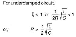
 For the parallel RLC circuit to be underdamped

Detailed Solution for Test: Second Order RLC Circuits - 1 - Question 3

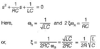
Characteristic equation of a parallel RLC circuit is

Test: Second Order RLC Circuits - 1 - Question 4

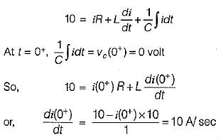
For the circuit shown below, the switch K is closed at t = 0,
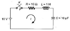
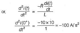
The value of the current and their derivatives for the above circuit at t = 0 were foundout and matched as given below:
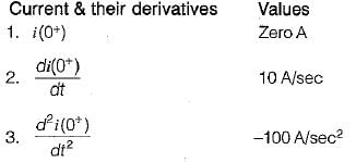
Which of the above are correctly matched ?

Detailed Solution for Test: Second Order RLC Circuits - 1 - Question 4

At t = 0+, inductor will act as open circuit therefore, i(0+) = 0 A.
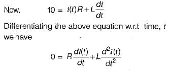
Applying KVL in the loop, we have

Test: Second Order RLC Circuits - 1 - Question 5

The energy in a network in Laplace domain is given by

​The initial and final values of power are respectively

Detailed Solution for Test: Second Order RLC Circuits - 1 - Question 5

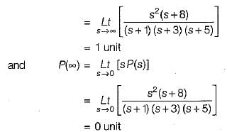
We know that,

Test: Second Order RLC Circuits - 1 - Question 6

A voltage is given by

The value of V(t→ ∞) is

Detailed Solution for Test: Second Order RLC Circuits - 1 - Question 6

Test: Second Order RLC Circuits - 1 - Question 7

 The voltage across a capacitor is given by

If the capacitor has the value of 2 F, initial value of current through it (at t = 0+) will be

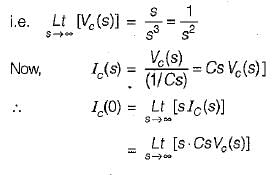
Detailed Solution for Test: Second Order RLC Circuits - 1 - Question 7

Hence, initial value of current through the capacitor = 2 A.

Test: Second Order RLC Circuits - 1 - Question 8

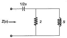
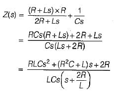
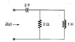
The impedance Z(s) in the circuit shown below is
 

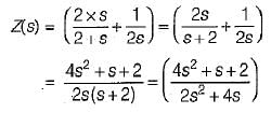
Detailed Solution for Test: Second Order RLC Circuits - 1 - Question 8

The given circuit in Laplace domain is shown below.

Test: Second Order RLC Circuits - 1 - Question 9

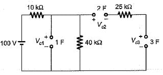
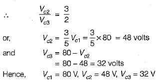
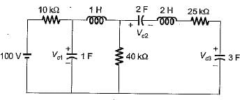
The voltage Vc1,Vc2 and Vc3 across the capacitors in the circuit shown below under steady-state, are respectively
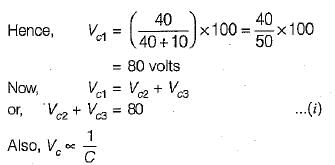
Detailed Solution for Test: Second Order RLC Circuits - 1 - Question 9

Under steady state condition inductors will act as short circuit while capacitors will act as open circuit.

Test: Second Order RLC Circuits - 1 - Question 10

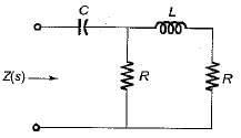
 The value of Z(s) in the circuit shown below is given by

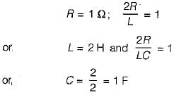
The values of R, L and Care respectively given by

Detailed Solution for Test: Second Order RLC Circuits - 1 - Question 10

On comparing the two values of Z(s), we get

25 docs|247 tests
Information about Test: Second Order RLC Circuits - 1 Page
In this test you can find the Exam questions for Test: Second Order RLC Circuits - 1 solved & explained in the simplest way possible. Besides giving Questions and answers for Test: Second Order RLC Circuits - 1, EduRev gives you an ample number of Online tests for practice

Top Courses for Electrical Engineering (EE)

Download as PDF

Top Courses for Electrical Engineering (EE)