Test: Thyristors - Electrical Engineering (EE) MCQ
10 Questions MCQ Test GATE Electrical Engineering (EE) Mock Test Series 2025 - Test: Thyristors

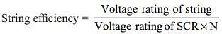
A thyristor switch has voltage rating of 700 V for each and 7 SCRs are connected in series for handling a voltage of 3800 V. The derating factor for this set of arrangement is

Generally inductor connected at the cathode end of SCR for _________ protection
| 1 Crore+ students have signed up on EduRev. Have you? Download the App |
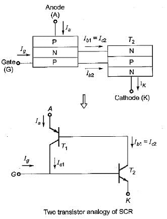
Assertion (A) : The operation of an SCR can be explained in a very simple way by considering it in terms of two transistors.
Reason (R) : in the two transistor analogy of the SCR, the SCR can be considered as an npn and a pnp transistor, where the collector of one transistor is attached to the emitter of the other and vice-versa.
Reason (R) : in the two transistor analogy of the SCR, the SCR can be considered as an npn and a pnp transistor, where the collector of one transistor is attached to the emitter of the other and vice-versa.
After firing an SCR, the gate pulse is removed. The current in the SCR will
An SCR having turn on time of 5 ms, latching current of 100 mA and holding current of 38 mA is triggered by a short duration pulse. What will be the minimum width, triggering pulse would require for successful turn ON of SCR
The main reason for connecting a pulse transformer at the output stage of a thyristor triggering circuit is to
|
25 docs|247 tests
|
|
25 docs|247 tests
|
Top Courses for Electrical Engineering (EE)


Important Questions for Thyristors
Thyristors MCQs with Answers
Online Tests for Thyristors GATE Electrical Engineering (EE) Mock Test Series 2025
|
© EduRev
|
Education Revolution
|


|


