Electrical Engineering (EE) Exam  >  Electrical Engineering (EE) Tests  >  GATE Electrical Engineering (EE) Mock Test Series 2025  >  Test: Combinational Logic Circuits - 2 - Electrical Engineering (EE) MCQ

Test: Combinational Logic Circuits - 2 - Electrical Engineering (EE) MCQ


Test Description

10 Questions MCQ Test GATE Electrical Engineering (EE) Mock Test Series 2025 - Test: Combinational Logic Circuits - 2

Test: Combinational Logic Circuits - 2 for Electrical Engineering (EE) 2024 is part of GATE Electrical Engineering (EE) Mock Test Series 2025 preparation. The Test: Combinational Logic Circuits - 2 questions and answers have been prepared according to the Electrical Engineering (EE) exam syllabus.The Test: Combinational Logic Circuits - 2 MCQs are made for Electrical Engineering (EE) 2024 Exam. Find important definitions, questions, notes, meanings, examples, exercises, MCQs and online tests for Test: Combinational Logic Circuits - 2 below.
Solutions of Test: Combinational Logic Circuits - 2 questions in English are available as part of our GATE Electrical Engineering (EE) Mock Test Series 2025 for Electrical Engineering (EE) & Test: Combinational Logic Circuits - 2 solutions in Hindi for GATE Electrical Engineering (EE) Mock Test Series 2025 course. Download more important topics, notes, lectures and mock test series for Electrical Engineering (EE) Exam by signing up for free. Attempt Test: Combinational Logic Circuits - 2 | 10 questions in 30 minutes | Mock test for Electrical Engineering (EE) preparation | Free important questions MCQ to study GATE Electrical Engineering (EE) Mock Test Series 2025 for Electrical Engineering (EE) Exam | Download free PDF with solutions
Test: Combinational Logic Circuits - 2 - Question 1

Consider the following statements:

1. When a MUX is used to implement a logic function, the logic variables are applied to the MUX’s data inputs.

2. The circuit for a DEMUX is basically the same as that for a decoder.

Of these:

Detailed Solution for Test: Combinational Logic Circuits - 2 - Question 1

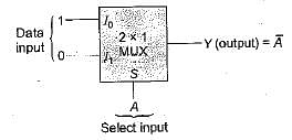
When a MUX is used to implement a logic function, the logic variables are applied to the MUX's select or control input.
For an example, if we want to implement a NOT gate using a 2 x 1 MUX, then the circuit will be represented as shown below:

Hence, statement-1 is not correct.

Statement-2 is correct because the internal circuit for a DEMUX (data distributor) and a decoder are basically same.

Test: Combinational Logic Circuits - 2 - Question 2

 Match List-I (Combinational Circuits) with List-ll (Applications) and select the correct answer using the codes given below the lists:

List-I
A. Decoder
B. Multiplexer
C. Encoder
D. Demultiplexer

List-ll
1. Serial to parallel converter
2. Analog to digital converter
3. Parallel to serial converter
4. Digital to analog converter
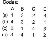
Detailed Solution for Test: Combinational Logic Circuits - 2 - Question 2

Decoder is a circuit which converts the digital signal into analog signal. Its input will be in digital form while the output will be a continuous sine wave or analog wave.
Encoders are combinational logic circuits and they are exactly opposite of decoders. They accept one or more inputs and generate a multi bit output code. Encoders perform exactly reverse operation than decoders. i.e analog to digital.
Multiplexer is a data selector which takes several inputs and gives a single output.In multiplexer we have 2n input lines and 1 output lines where n is the number of selection lines.
Demultiplexer is a data distributor which takes a single input and gives several outputs.In demultiplexer we have 1 input and 2n output lines where n is the selection line.

1 Crore+ students have signed up on EduRev. Have you? Download the App
Test: Combinational Logic Circuits - 2 - Question 3

The logic function F(A, B, C) = Σm(1, 3, 5, 6) can be implemented using

Detailed Solution for Test: Combinational Logic Circuits - 2 - Question 3

Given function,

 has three variables. Hence, it can be implemented using a multiplexer ( 4 x 1 M U X) with two select inputs and four data inputs.
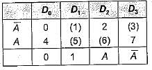
The implementation table is shown below:

Now, the given three variable functions can be implemented using 4-to-1 multiplexer as shown below:

Hence, for implementation of given function we require one 4 x 1 MUX and a NOT gate

Test: Combinational Logic Circuits - 2 - Question 4

In a binary adder with two inputs X and Y, the correct set of logical expression for the output S (sum) and C (carry) are respectively

Detailed Solution for Test: Combinational Logic Circuits - 2 - Question 4

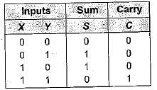
The truth table for half adder is shown below

Here, sum output   and carry output is C= XY

Test: Combinational Logic Circuits - 2 - Question 5

A certain multiplexer can switch one of 32 data inputs to its output. The number of control inputs in this multiplexer

Detailed Solution for Test: Combinational Logic Circuits - 2 - Question 5

No. of input lines = 2m (where, m = No. of select/ control inputs) or, 32 = 2m or m=5.

Test: Combinational Logic Circuits - 2 - Question 6

Consider the following statements associated with the use of various adder circuits:
1. A ripple carry adder is a parallel adder in which the carry-out of each full-adder is the carry-in to the next most significant adder.
2. Serial adders are used where speed is more important than circuit minimization.
3. The look-ahead carry adder speeds up the process by eliminating the ripple carry.
4. Serial adders are faster than parallel adders

Which of the statements given above are correct?

Detailed Solution for Test: Combinational Logic Circuits - 2 - Question 6
  • Serial adders are used where circuit minimization is more important than speed because they require one clock pulse for each pair of bits added and hence slower than parallel adders. Thus, statements 2 and 4 are not correct.
  • Statements 1 and 3 are correct.
Test: Combinational Logic Circuits - 2 - Question 7

Assertion (A): The multiplexer can be viewed as a function generator.
Reason (R): The multiplexer acts like a digitally controlled multi-position switch

Detailed Solution for Test: Combinational Logic Circuits - 2 - Question 7
  • The multiplexer can be viewed as a function generator because we can easily set or change the logic function it implements.
  • The multiplexer acts like a digitally controlled multi-position switch because the digital code applied to the SELECT inputs determine which data inputs will be switched to the output.

Hence, both assertion and reason are correct but reason is not the correct explanation of assertion.

Test: Combinational Logic Circuits - 2 - Question 8

Assertion (A): Using a decoder could have advantages over using a multiplexer.
Reason (R): The decoder is more economical in cases where non-trivial, multiple-output expressions of the same input variables are required

Detailed Solution for Test: Combinational Logic Circuits - 2 - Question 8

In cases where non-trivial, a multiple-output expressions of the same input variables are required, a decoder could be advantageous than a multiplexer because in such cases, one multiplexer is required for each output, whereas it is likely that only one decoder supported with a few gates would be required.

Test: Combinational Logic Circuits - 2 - Question 9

Assertion (A): The speed of operation of the parallel binary adder is high.

Reason (R): The parallel binary adder is said to generate its output immediately after the inputs are applied.

Detailed Solution for Test: Combinational Logic Circuits - 2 - Question 9

The speed of operation of the parallel binary adder is limited by the carry propagation delay through all stages. Hence, assertion is not correct.

Test: Combinational Logic Circuits - 2 - Question 10

A multiplexer has

25 docs|247 tests
Information about Test: Combinational Logic Circuits - 2 Page
In this test you can find the Exam questions for Test: Combinational Logic Circuits - 2 solved & explained in the simplest way possible. Besides giving Questions and answers for Test: Combinational Logic Circuits - 2, EduRev gives you an ample number of Online tests for practice

Top Courses for Electrical Engineering (EE)

Download as PDF

Top Courses for Electrical Engineering (EE)