Analog Electronics - 2 - Electronics and Communication Engineering (ECE) MCQ
10 Questions MCQ Test GATE ECE (Electronics) Mock Test Series 2025 - Analog Electronics - 2
For the transistor circuit shown below:
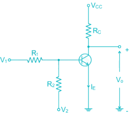
If V1 = 1V and V2 = -12V R1 = 15k and R2 = 100k Rc = 2.2 k Vcc = 12V Then the Region of operation of transistor is

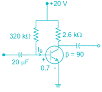
In the DC fixed bias circuit shown below the operating point is
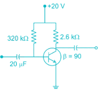

The Miller effect in the context of a Common Emitter amplifier explains
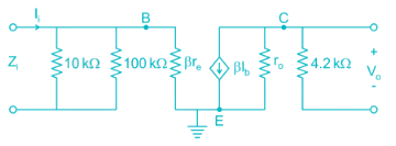
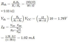
For the network shown in the figure. Find the Input independence Zi (kΩ) [Use appropriate approximation]
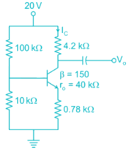
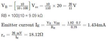
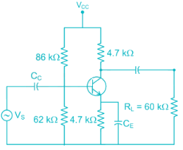
The voltage gain of the amplifier shown if β = 250 is approximately
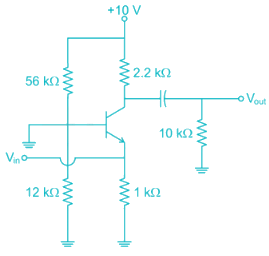
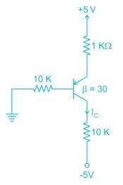
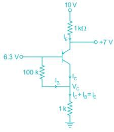
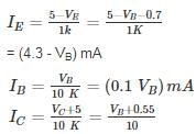
For the pnp transistor shown, the collector current IC is_______ mA.
(Assume VEB(ON) = VEB(Sat) = 0.7 V)
VEC(Sat) = 0.2 V
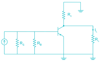
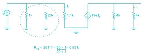
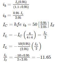
For the circuit shown in the figure if RC = 4 kΩ, RL = 4 kΩ, RB = 20 kΩ, Rs = 1 kΩ and transistor parameter are magnitude of hie = 1.1 kΩ, hfe = 50
The current gain is:
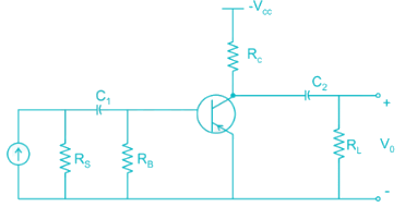
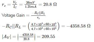
For the Common emitter configuration circuit shown below, if IC = 1.25 mA, then the magnitude of voltage gain is_______
The reverse leakage current of the transistor when connected in CB Configuration is 0.3 μ A and it is 18 μA when the same transistor is connected in CE Configuration the value of α and β of the transistor for a base current of 40 mA will be respected.
|
25 docs|263 tests
|


