Electronics and Communication Engineering (ECE) Exam  >  Electronics and Communication Engineering (ECE) Tests  >  GATE ECE (Electronics) Mock Test Series 2025  >  Analog Electronics - 5 - Electronics and Communication Engineering (ECE) MCQ

Analog Electronics - 5 - Electronics and Communication Engineering (ECE) MCQ


Test Description

10 Questions MCQ Test GATE ECE (Electronics) Mock Test Series 2025 - Analog Electronics - 5

Analog Electronics - 5 for Electronics and Communication Engineering (ECE) 2025 is part of GATE ECE (Electronics) Mock Test Series 2025 preparation. The Analog Electronics - 5 questions and answers have been prepared according to the Electronics and Communication Engineering (ECE) exam syllabus.The Analog Electronics - 5 MCQs are made for Electronics and Communication Engineering (ECE) 2025 Exam. Find important definitions, questions, notes, meanings, examples, exercises, MCQs and online tests for Analog Electronics - 5 below.
Solutions of Analog Electronics - 5 questions in English are available as part of our GATE ECE (Electronics) Mock Test Series 2025 for Electronics and Communication Engineering (ECE) & Analog Electronics - 5 solutions in Hindi for GATE ECE (Electronics) Mock Test Series 2025 course. Download more important topics, notes, lectures and mock test series for Electronics and Communication Engineering (ECE) Exam by signing up for free. Attempt Analog Electronics - 5 | 10 questions in 30 minutes | Mock test for Electronics and Communication Engineering (ECE) preparation | Free important questions MCQ to study GATE ECE (Electronics) Mock Test Series 2025 for Electronics and Communication Engineering (ECE) Exam | Download free PDF with solutions
Analog Electronics - 5 - Question 1

The lower 3-dB frequency of the amplifier circuit shown below is
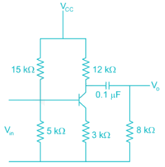
Detailed Solution for Analog Electronics - 5 - Question 1

The lower 3 dB frequency ω

*Answer can only contain numeric values
Analog Electronics - 5 - Question 2

The efficiency of a class B amplifier with a supply voltage of 24V and peak output voltage Vo = 22V is _______%


Detailed Solution for Analog Electronics - 5 - Question 2

For a class B amplifier with VCC = 24 V and VO = 22 V efficiency η (in %) is given by

Analog Electronics - 5 - Question 3

In class AB amplifiers, the current flows through the active device for

Detailed Solution for Analog Electronics - 5 - Question 3

For class A the angle of excursion is 3600

For class B the angle of excursion is 1800

For class AB the angle of excursion is >1800 and < 3600

For class C the angle of excursion is less than 1800

*Answer can only contain numeric values
Analog Electronics - 5 - Question 4

A class – A transformer coupled, the Transistor power amplifier is Required to deliver a power output of 10 watts, the maximum power rutting of the transistor should not be less than –


Detailed Solution for Analog Electronics - 5 - Question 4

PiDC = Poac + PTr

Pooc = 10 W

η = 50% for class-A transformer coupled

Analog Electronics - 5 - Question 5

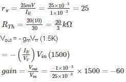
In the following transistor circuit,VBE = 0.7 V, rπ = 25 mV / IE, and β and all the capacitances are very large

The mid-band voltage gain of the amplifier is approximately
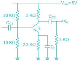
Detailed Solution for Analog Electronics - 5 - Question 5

Apply ac analysis to calculate gain


∴ Option (4) is correct.

Analog Electronics - 5 - Question 6

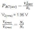
A Transformer coupled class A amplifier has a loudspeaker of 8 Ω connected or across its secondary. The Q point of collector current is 140 mA. The Turns ratio of the transformer is 3:1. If the power delivered to the load is 0.48 W. Then the rms voltage at the primary and efficiency of the transformer is
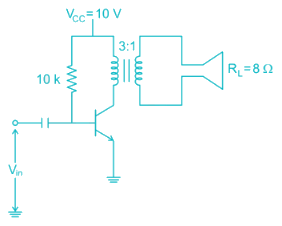
Detailed Solution for Analog Electronics - 5 - Question 6

Given

PAC(secondary) = 0.48 W

ICQ = 140 mA

RL = 8 Ω

PAC(sec) = PAC(primary)

PAC(primary) = 0.48 W

V1(rms) = 1.96 × 3 = 5.88 V

output DC power

PDC = VCC ICQ

= 10(140 × 10-3)

= 1.4 W

*Answer can only contain numeric values
Analog Electronics - 5 - Question 7


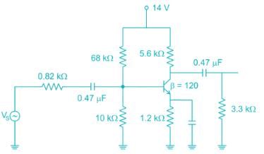
The low frequency cut-off frequency due to source capacitance (0.47 uF) is ________ Hz

Take VT = 26 mV. ( assume 0.47 uF capacitance at input is source capacitance )


Detailed Solution for Analog Electronics - 5 - Question 7

The cut-off frequency due to source capacitance


Where RS = source resistance

Ri = Input impedance

Where Ri = R1 // R2// βre

In DC bias values


Taking KVL in base-emitter path

VB - VBE - IE (1.2 Ω) = 0


IE = 0.917 mA

∴ Ri = R1 // R2 // βve

= 10 kΩ // 68 kΩ // (120 × 28.36) Ω

≅ 2.44 k Ω

= 103. 87 Hz

Analog Electronics - 5 - Question 8

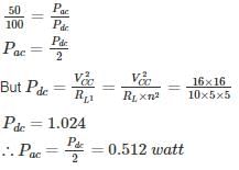
For a class A transformer coupled amplifier calculate the maximum power delivered to the load when its RL = 10 Ω, n = 5 (turns ratio) and VCC = 16 V

Detailed Solution for Analog Electronics - 5 - Question 8

For class A transformer coupled amplifier

η = 50%

Analog Electronics - 5 - Question 9

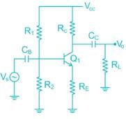
The amplifier is shown below as a voltage gain of -2.5, and input resistance of 10 kΩ and a lower 3 dB cut-off frequency of 20 Hz. Which on the following statements is TRUE when the emitter resistance RE is doubled?
Detailed Solution for Analog Electronics - 5 - Question 9

The Voltage Gain of the common emitter amplifier is equal to the ratio of the change in the input voltage to the change in the amplifiers output voltage. Then ΔVL is Vout and ΔVB s Vin. But voltage gain is also equal to the ratio of the signal resistance in the Collector to the signal resistance in the Emitter and is given as:

Voltage gain 
∴ If RE increase then voltage gain will decrease and –ve feedback increase

*Answer can only contain numeric values
Analog Electronics - 5 - Question 10

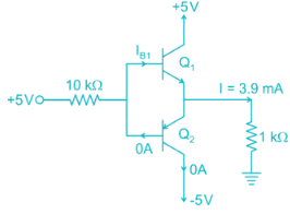
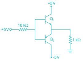
In the circuit shown in figure find the voltage drop (in V) in 1 kΩ Resistor. Assume β = 100


Detailed Solution for Analog Electronics - 5 - Question 10


Assume that Q2 in an. It fallows that current will flow from ground through the 1kΩ Resistor into the emitter of Q2. Thus the base of Q2 will be at –Ve voltage and base current will be flowing out of the through the 10 kΩ resistor and into +5V supply. This is impossible, since if the base is negative. Current in the 10 kΩ resistor will have to flow into the base. Thus we conclude that our original assumption that Q2 is ON is incorrect. It follows that Q2 will be off and Q1 will be ON.

25 docs|263 tests
Information about Analog Electronics - 5 Page
In this test you can find the Exam questions for Analog Electronics - 5 solved & explained in the simplest way possible. Besides giving Questions and answers for Analog Electronics - 5, EduRev gives you an ample number of Online tests for practice
Download as PDF