Test: JK Flip Flop - Electrical Engineering (EE) MCQ
15 Questions MCQ Test Analog and Digital Electronics - Test: JK Flip Flop
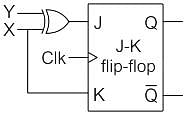
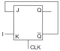
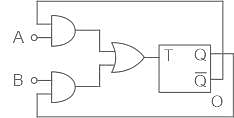
Consider the circuit shown below:

The characteristic equation of the new flip-flop created from the above circuit is

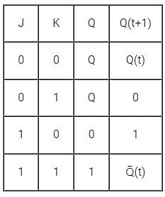
For which of the following flip-flops, the output is clearly defined for all combinations of two inputs.
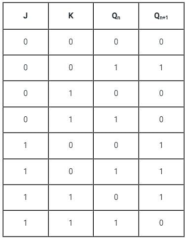
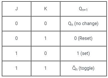
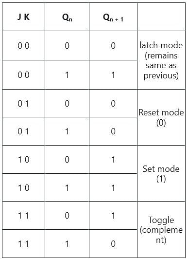
The functional difference between SR flip-flop and JK flip-flop is that
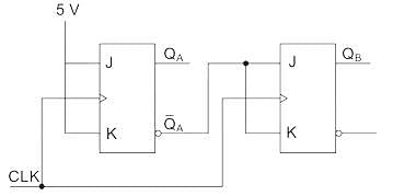
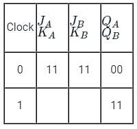
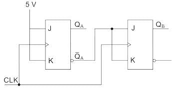
The current state QA QB of a two JK flip-flop system is 00. Assume that the clock rise-time is much smaller than the delay of the JK flip-flop. The next state of the system is.
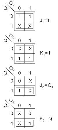
A synchronous counter using two J – K flip flops that goes through the sequence of states: Q1 Q2 = 00 → 10 → 01 → 11 → 00 …. is required. To achieve this, the inputs to the flip flops are
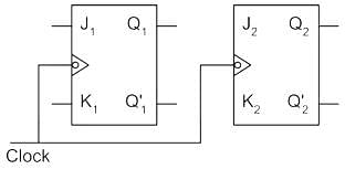
The output Qn of a JK flip-flop is zero. It changes to 1 when a clock pulse is applied. The input Jn and Kn are respectively
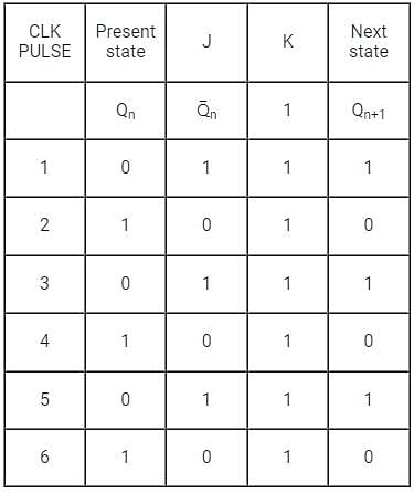
In a JK flip-flop we have J = Q̅ and K = 1 Assuming the flip-flop was initially cleared and then clocked for 6 pulses, the sequence at the Q output will be:
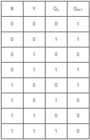
An X-Y flip-flop whose characteristic table is given below is to be implemented using a J-K flip-flop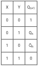
This can be done using-
A J-K flip-flop can be obtained from the clocked S-R flip-flop by augmenting ___________
The phenomenon of interpreting unwanted signals on J and K while Cp (clock pulse) is HIGH is called ____
A J-K flip-flop with J = 1 and K = 1 has a 20 kHz clock input. The Q output is ________
Four J-K flip-flops are cascaded with their J-K inputs tied HIGH. If the input frequency (fin) to the first flip-flop is 32 kHz, the output frequency (fout) is ________
What is represented by the digital circuit given in the figure below:
|
137 videos|144 docs|71 tests
|


