Electrical Engineering (EE) Exam  >  Electrical Engineering (EE) Tests  >  Digital Electronics  >  Test: Logic Gates - 2 - Electrical Engineering (EE) MCQ

Test: Logic Gates - 2 - Electrical Engineering (EE) MCQ


Test Description

15 Questions MCQ Test Digital Electronics - Test: Logic Gates - 2

Test: Logic Gates - 2 for Electrical Engineering (EE) 2024 is part of Digital Electronics preparation. The Test: Logic Gates - 2 questions and answers have been prepared according to the Electrical Engineering (EE) exam syllabus.The Test: Logic Gates - 2 MCQs are made for Electrical Engineering (EE) 2024 Exam. Find important definitions, questions, notes, meanings, examples, exercises, MCQs and online tests for Test: Logic Gates - 2 below.
Solutions of Test: Logic Gates - 2 questions in English are available as part of our Digital Electronics for Electrical Engineering (EE) & Test: Logic Gates - 2 solutions in Hindi for Digital Electronics course. Download more important topics, notes, lectures and mock test series for Electrical Engineering (EE) Exam by signing up for free. Attempt Test: Logic Gates - 2 | 15 questions in 45 minutes | Mock test for Electrical Engineering (EE) preparation | Free important questions MCQ to study Digital Electronics for Electrical Engineering (EE) Exam | Download free PDF with solutions
Test: Logic Gates - 2 - Question 1

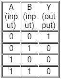
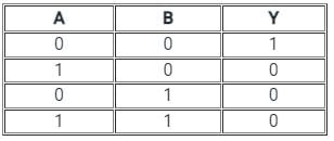
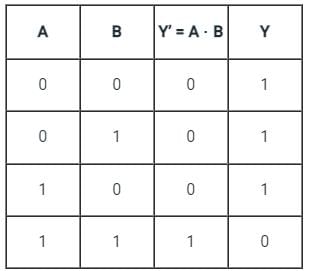
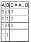
The truth table given below corresponds to-

Detailed Solution for Test: Logic Gates - 2 - Question 1

CONCEPT:

  • Truth table: A truth table is a mathematical table used to represent the output of a given function based on the combination of input variables.
    • A truth table has two columns: the first column shows the combination of input variables and the last column shows the final output for each input.
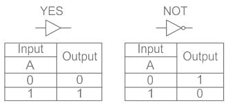
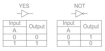
  • Logic gate: Logic gates are the basic building blocks of a digital system.
    • ​A logic gate works on the principle of a Boolean function which is a logical operation performed using one or more binary inputs that produce a single binary output.
    • The boolean function uses only two variables - zero or one.
    • The relationship between these inputs and the output is based on a certain logic. Based on this, logic gates are given names.
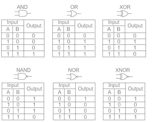
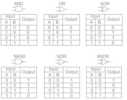
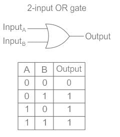
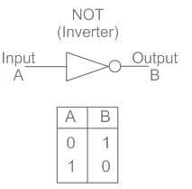
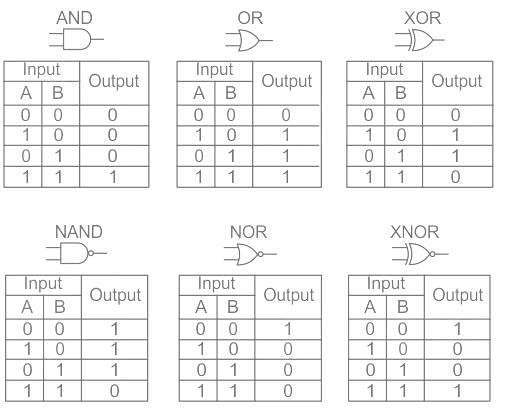
    • A few logic gates along with their symbol and truth table are as follows:

The given truth table matches with the NOR logic gate.

Test: Logic Gates - 2 - Question 2

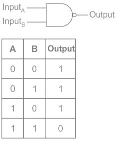
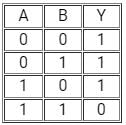
The truth table given below is for

(A and B are the inputs, Y is the output)
Detailed Solution for Test: Logic Gates - 2 - Question 2

CONCEPT:

  • Truth table: A truth table is a mathematical table used to represent the output of a given function based on the combination of input variables.
    • A truth table has two columns: the first column shows the combination of input variables and the last column shows the final output for each input.
  • Logic gate: Logic gates are the basic building blocks of a digital system.
    • ​A logic gate works on the principle of a Boolean function which is a logical operation performed using one or more binary inputs that produce a single binary output.
    • The boolean function uses only two variables - zero or one.
    • The relationship between these inputs and the output is based on a certain logic. Based on this, logic gates are given names.
    • A few logic gates along with their symbol and truth table are as follows:

The given truth table matches with the NAND logic gate.

1 Crore+ students have signed up on EduRev. Have you? Download the App
Test: Logic Gates - 2 - Question 3


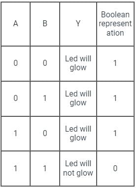
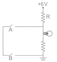
If the glow of the bulb is considered an output, the correct Boolean operation represented by the circuit diagram drawn will be:
Detailed Solution for Test: Logic Gates - 2 - Question 3

From the given circuit we can see that,

  • Two Keys are connected parallel to a LED and a resistor.
  • Hence if any of the keys is open, no current will flow through keys and hence bulb will glow
  • But if both the keys are closed current will start flowing from keys instead of LEDs, since current (I) will always flow where resistance is minimum.
  • Which means the truth table for the given circuit can be given as
  • Here 1 shows key is closed and current can flows through it
  • And 0 shows key is open and current can’t flow through it

Test: Logic Gates - 2 - Question 4

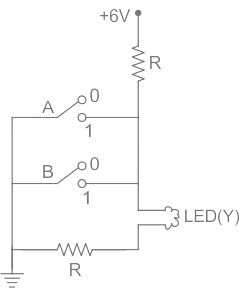
The circuit diagram shown here corresponds to the logic gate
Detailed Solution for Test: Logic Gates - 2 - Question 4

CONCEPT:

  • OR gate - The OR gate is defined as the gate in which if one of the inputs is true then the result will also true.
  • AND gate - The AND gate is defined as the gate in which if one of the inputs is false then the result will also false.
  • NOT gate - The NOT gate is defined as the output attains state 1 if and only if the input does not attain state 1.
  • NOR gate - NOR gate is defined as it is the combination of NOT and OR gate.

CALCULATION:
Let us the different cases.
Case I - When A = 0, B = 0
The LED will glow.
Therefore, Y = 1
Case II - When A = 1, B = 0
The LED will not glow.
Therefore, Y = 0
Case III - When A = 0, B = 1
The LED will not glow.
Therefore, Y = 0
Case IV - When A = 1, B = 1
The LED will glow.
Therefore, Y = 0
The truth table is written as;

Here we see the results it will show the nature of NOR.
Hence, option 3) is the correct answer.

Test: Logic Gates - 2 - Question 5

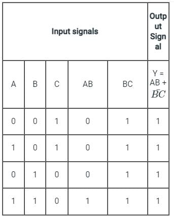
For the given circuit, the input digital signals are applied at the terminals A, B and C. What would be the output at the terminal y ?
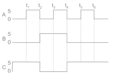
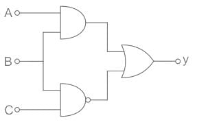
Detailed Solution for Test: Logic Gates - 2 - Question 5

Concept:
Logic gates are:

1.AND Gate

2. NAND Gate

3. OR Gate

Calculation:
Output of combination of logic gates is given as


So the output y is high i.e., 1.
Hence, Output voltage is V0 = 5 V.

Test: Logic Gates - 2 - Question 6

Identify the logic gate

Detailed Solution for Test: Logic Gates - 2 - Question 6

Correct answer is D.

Test: Logic Gates - 2 - Question 7

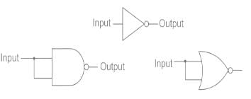
When both the input signals A and B of the NOR & NAND gate are connected together, The output of the resultant circuit will be equivalent to

Detailed Solution for Test: Logic Gates - 2 - Question 7

CONCEPT:

  • Logic gate: The digital circuit that can be analyzed with the help of Boolean algebra is called a logic gate or logic circuit.
  • A logic gate has two or more inputs but only one output.
  • Logic gates works on the ruth table.

When both the input signals A and B of NOR & NAND gate are connected together, we have one common input connection hence the resultant output will be NOT gated.
As shown when both the inputs are combined in either NAND or NOR gate, they both will behave like a NOT gate

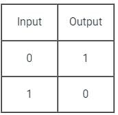
This will be the truth table for both NAND and NOR logic gate when their inputs are connected.

Test: Logic Gates - 2 - Question 8

What will be the output of the combination of AND gate and NOT gate if the inputs are A and B?

Detailed Solution for Test: Logic Gates - 2 - Question 8

CONCEPT
Logic gates: 

  • It is an electric circuit, which works on simple Boolean algebra to perform a logical operation for one or more binary inputs that produce a single binary output.

Types of Logic gates:
AND Gate: If both the inputs are high, it produces a high output.

  • The Boolean algebra for AND gate is X = A. B

OR gate: If any of the input is high, it produces a high output.

  • The Boolean algebra for OR gate is X = A + B

NOT gate: It inverts the input. Whatever the input is given, it changes its value at the output.

  • The Boolean algebra for NOT gate is X = X̅

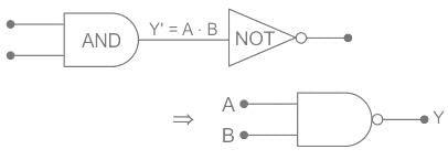
  • The combination of AND gate and NOT gate gives the NAND gate.
  • he Boolean algebra for AND gate is 


Therefore option 3 is correct.

Test: Logic Gates - 2 - Question 9

Which one is the Universal Gate?

Detailed Solution for Test: Logic Gates - 2 - Question 9

The correct answer is NOR gate.
Concept:

  • A Universal Gate is a gate by which every other gate can be realized.
  • AND, OR, NOT, etc. are basic gates.
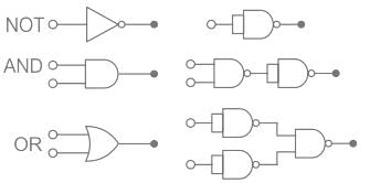
  • NAND, NOR  are the universal gate.

NOT, AND and OR gate realization using NAND gate is as shown:

Test: Logic Gates - 2 - Question 10

Identify the logic gate carried out by the following circuit.

Detailed Solution for Test: Logic Gates - 2 - Question 10

CONCEPT:

  • Logic gate: The digital circuit that can be analysed with the help of Boolean algebra is called a logic gate or logic circuit.
  • A logic gate has two or more inputs but only one output.

Combination of Logic Gates

The above combination of the logic gate is the NAND gate.

Test: Logic Gates - 2 - Question 11

Which of the following is not true about the Logic gate?

Detailed Solution for Test: Logic Gates - 2 - Question 11

CONCEPT:

  • Logic gate: The digital circuit that can be analyzed with the help of Boolean algebra is called a logic gate or logic circuit.
  • A logic gate has two or more inputs but only one output.
  • There are primarily three logic gates namely the OR gate, the AND gate, and the NOT gate.

A logic gate has one or more inputs but only one output. Thus, option 2 is correct.
It is an electronic device that implements a Boolean function. Thus option 1 is correct.
A logic gate follows a logical relationship between input and output voltages. Thus option 3 is incorrect.

Test: Logic Gates - 2 - Question 12

The function of a NOT logic gate is to

Detailed Solution for Test: Logic Gates - 2 - Question 12

CONCEPT:

  • Logic gate: Logic gates are the basic building blocks of a digital system.
    • ​A logic gate works on the principle of a Boolean function which is a logical operation performed using one or more binary inputs that produce a single binary output.
    • The boolean function uses only two variables - zero or one.
    • The relationship between these inputs and the output is based on a certain logic. Based on this, logic gates are given names.
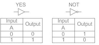
    • A few logic gates along with their symbol and truth table are as follows:


  • The high and low inputs correspond to 1 and 0 respectively.
  • In a NOT gate, a low output is obtained from a high input and vice versa.
  • Therefore, as inferred from the truth table of the NOT gate, it inverts the input signal.
Test: Logic Gates - 2 - Question 13

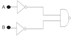
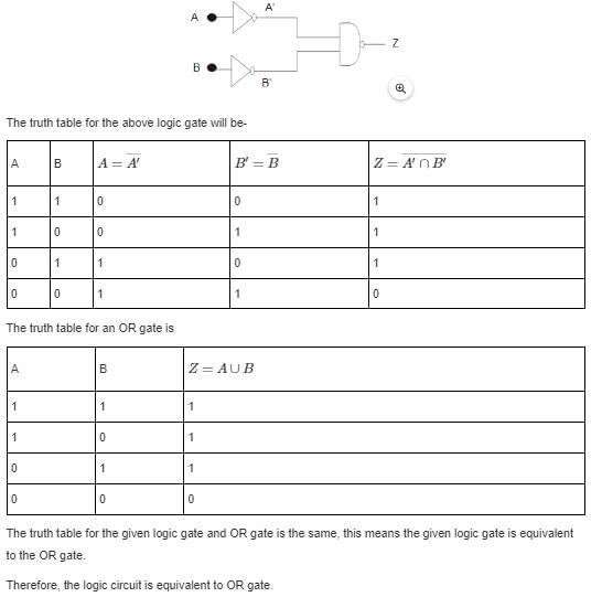
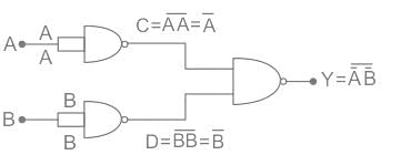
Identify the logic operation carried out by the following circuit.
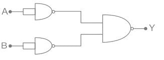
Detailed Solution for Test: Logic Gates - 2 - Question 13

Concept:
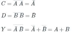
De Morgan’s law states that:


This is OR gate. So option 4 is correct.

Test: Logic Gates - 2 - Question 14

Choose the incorrect statement regarding logic gates.

Detailed Solution for Test: Logic Gates - 2 - Question 14

CONCEPT:

  • Logic gate: The digital circuit that can be analyzed with the help of Boolean algebra is called a logic gate or logic circuit.
  • A logic gate has two or more inputs but only one output.
  • Logic gates work on the truth table.

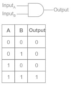
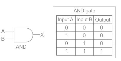
AND Gate: The Logic AND Gate is a type of digital logic circuit whose output goes 1 (HIGH) only when all of its inputs are 1 (HIGH)


The truth table for AND gate:

  • As the logic gates give only one output. It is not the continuous output giving element. But the fuse should work continuously. That's why the logic gates can’t be used as a fuse in an electric circuit. So statement 3 is wrong. So option 3 is correct.
  • As the logic gates give only one output. It is not the continuous output giving element. In case of an on or off alarms, we just need only one output, either on or off. That's why the logic gates can be used to on or off the alarm. So statement 2 is correct.
  • The logic gates work on the truth table as shown in the example on the concept part because it can give either yes or no as output. So statement 1 is correct.
Test: Logic Gates - 2 - Question 15

Identify the logic gate

Detailed Solution for Test: Logic Gates - 2 - Question 15

CONCEPT:

  • Logic gate: The digital circuit that can be analysed with the help of Boolean algebra is called a logic gate or logic circuit.
  • A logic gate has two or more inputs but only one output.
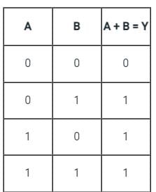
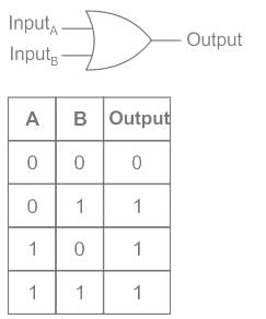
OR gate: It is a digital circuit having two or more inputs but only one output.
It gives a high output if either input A or B or both are high (1) otherwise it gives a low output (0).
It is described by the Boolean expression: A + B = Y
The above logic gate is the OR gate.
The truth table of OR gate:

115 videos|71 docs|58 tests
Information about Test: Logic Gates - 2 Page
In this test you can find the Exam questions for Test: Logic Gates - 2 solved & explained in the simplest way possible. Besides giving Questions and answers for Test: Logic Gates - 2, EduRev gives you an ample number of Online tests for practice

Top Courses for Electrical Engineering (EE)

115 videos|71 docs|58 tests
Download as PDF

Top Courses for Electrical Engineering (EE)