Test: Firing Circuits - Electrical Engineering (EE) MCQ
30 Questions MCQ Test Power Electronics - Test: Firing Circuits

In a single pulse semi-converter using two SCRs, the triggering circuit must produce
In a 3-phase full converter using six SCRs, gating circuit must provide

In the complete firing circuit, the driver circuit consists of
Find the average gate power dissipation (Pgav) when the maximum allowable gate power dissipation (Pgm) = 10 kW, with a duty cycle = 50 %.
The magnitude of gate voltage and gate current for triggering an SCR is
Find the amplitude of the gate current pulse, when the gate-cathode curve is given by the relation Vg = [(1+10) x Ig] The peak gate drive power is 5 Watts.
The gate-cathode curve for an SCR is given by the relation Vg = (1+10)Ig. The gate voltage source is a rectangular pulse of peak value 15 V and current = 0.659 A. Find the source resistance.
Find the triggering frequency when the average gate power dissipation = 0.3 W and the peak gate drive power is 5 Watts. The gate source has a pulse width of 20 μsec duration.
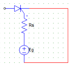
For a R firing circuit, the maximum value of source voltage is 100 V. Find the resistance to be inserted to limit the gate current to 2 A.
In case of an RC half wave triggering circuit, the firing angle can be ideally varied between
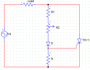
In case of a R firing with R2 as the variable resistance, Vgp (peak of gate voltage) and Vgt(gate triggering voltage) the value of R2 is so adjusted such that
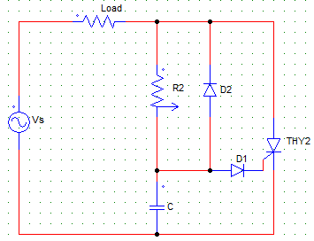
The figure shown below is that of an RC firing circuit.
In case of negative cycle at Vs, the capacitor C
Find the value of R in case of an RC firing circuit which is to be turned on with a source voltage of 150 V and the following parameters.
Igt = 2A
Vd = 1.5V
Vgt = 125 V
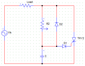
For the following RC triggering circuit with R load and a firing angle of α, the voltage across the R load is zero for
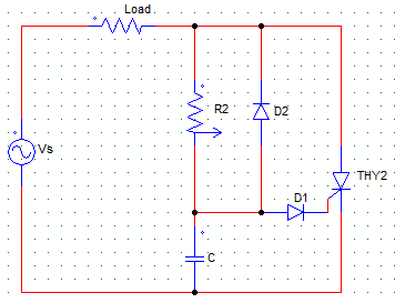
For the following RC triggering circuit with R load and a firing angle of α, the voltage across the SCR (thy2) will be zero for
In case of an RC full wave firing circuit with R load, the voltage across the load is zero for____________
For an RC full wave firing circuit the empirical formula for calculating the value of RC is
Pulse triggering can be only used by the _____________ type of triggering circuit
In the UJT firing circuit, the pulses are generated while the
Find the value of the charging resistor in case of a UJT firing circuit with firing frequency of 2 kHz, C = 0.04 μF, η = 0.72
|
5 videos|50 docs|46 tests
|


Important Questions for Firing Circuits
Firing Circuits MCQs with Answers
Online Tests for Firing Circuits Power Electronics
|
© EduRev
|
Education Revolution
|


|


