Test: Steady State Time Domain Analysis of Type-A Chopper - Electrical Engineering (EE) MCQ
5 Questions MCQ Test Power Electronics - Test: Steady State Time Domain Analysis of Type-A Chopper

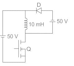
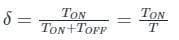
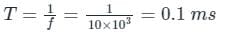
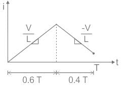
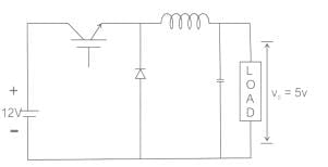
In the dc-dc converter circuit shown, switch Q is switched at a frequency of 10 kHz with a duty ratio of 0.6. All components of the circuit are ideal, and the initial current in the inductor is zero. Energy stored in the inductor in mJ (rounded off to 2 decimal places) at the end of 10 complete switching cycles is ________


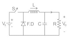
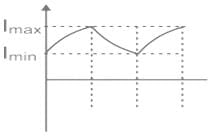
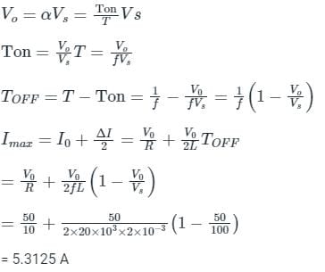
For the circuit shown in the figure, assume L to be large enough to ensure linear growth and decay of the current through it and have continuous current. The maximum value of the load current in amperes is _________ (Vs = 100 V, Vo = 50 V, L = 2mH, f = 20 kHz, R = 10 Ω)

| 1 Crore+ students have signed up on EduRev. Have you? Download the App |
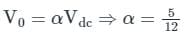
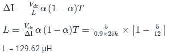
In the circuit shown below, if load R = 500 Ω, switching frequency is 25 kHz and peak to peak ripple current of inductor is limited to 0.9 A then the filter inductance L is
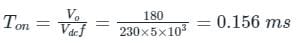
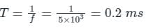
In chopper circuit the average value of output voltage is controlled by time ratio control (TRC) method. The chopper is operated at a frequency of 5kHz on a 230 V d.c. supply. If the load voltage is 180 V, then the blocking period of thyristor in each cycle is___(in μsec)
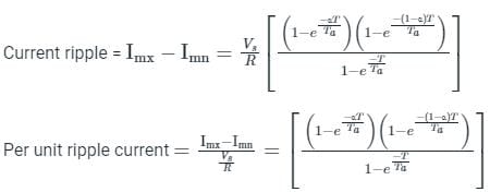
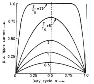
A dc chopper is fed from constant voltage mains. The duty ratio α of the chopper is progressively increased while the chopper feeds RL load. The per unit current ripple would
|
5 videos|50 docs|46 tests
|
|
5 videos|50 docs|46 tests
|
Top Courses for Electrical Engineering (EE)


Important Questions for Steady State Time Domain Analysis of Type-A Chopper
Steady State Time Domain Analysis of Type-A Chopper MCQs with Answers
Online Tests for Steady State Time Domain Analysis of Type-A Chopper Power Electronics
|
© EduRev
|
Education Revolution
|


Follow Us
|