Alternating Current, Class 12, Chapter Notes, Physics (IIT - JEE & AIPMT)

Alternating Current and its Average and RMS Value - Alternating Current, Class 12, Physics
Alternating Current
1. Alternating Current
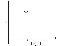
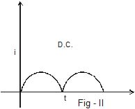
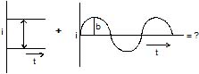
Until now, we have studied only circuits with direct current (dc) which flows only in one direction (as shown in fiugre I and II). The primary source of emf in such circuit is a battery. When a resistance is connected across the terminals of the battery, a current is established in the circuits, which flows in a unique direction from the positive terminal to the negative terminal via the external resistance.
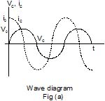
But most of the electric power generated and used in the world is in the form ofalternating current (ac), the magnitude of which changes continuously with time and direction is reversed periodically (as shown in figure III & IV)and it is given by
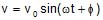
i = i0 sin (ωt + φ)
Here i is instantaneous value of current i.e., the magnitude of current at any instant of time and i0 is the maximum value of current which is called peak current or the current amplitude and the current repeats its value after each time interval T =  as shown in figure. This time interval is called the time period and w is angular frequency which is equal to 2π times of frequency f.
ω = 2πf
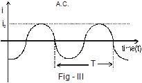
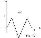
The current is positive for half the time period and negative for remaining half period. It means that the direction of current is reversed after each half time period. The frequency of ac in India is 50 Hz.
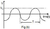
An alternating voltage is given by
V = V0 sin (ωt + φ)
It also varies alternatively as shown in the figure (b), where V is instantaneous voltage and V0 is peak voltage. It is produced by ac generator also called as ac dynamo.
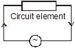
AC Circuit : An ac circuit consists of circuit element i.e., resistor, capacitor, inductor or any combination of these and a generator that provides the alternating current as shown in figure. The ac source is represented by symbol  in the circuit.
2. AVERAGE AND RMS VALUE OF ALTERNATING CURRENT
2.1 Average current (Mean current)
As we know an alternating current is given by
i = i0 sin (ωt + f) ...(1)
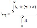
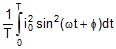
The mean or the average value of ac over any time T is given by

Using equation (1)
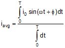
In one complete cycle, the average current
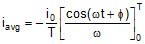 = -
= -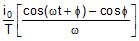 =
= 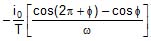 = 0 (as ωT = 2π)
Since ac is positive during the first half cycle and negative during the other half cycle so iavg will be zero for long time also. Hence the dc instrument will indicate zero deflection when connected to a branch carrying ac current. So it is defined for either positive half cycle or negative half cycle.
 =
= 
 0.637 i0
Similarly Vavg = 
 0.637 V0
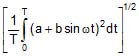
Ex.1 If a direct current of value a ampere is superimposed on an alternating current i = b sin wt flowing through a wire, what is the effective value of the resulting current in the circuit ?
Sol. As current at any instant in the circuit will be,
i = idc + iac = a + b sin ωt
So, ieff = 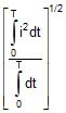 =
= 
i.e., = 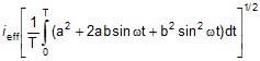
but as
 = 0 and
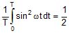
So, ieff = 
2.2 R.M.S Value of alternating current
The notation rms refers to root mean square, which is given by square root of mean of square current.
i.e., 
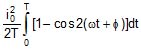
i2avg = 
=  =
= 
= 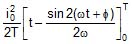 =
=
 =
= 
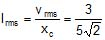
irms =  » 0.707 i0
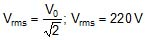
Similarly the rms voltage is given by
Vrms =  » 0.707 V0
The significance of rms current and rms voltage may be shown by considering a resistance R carrying a current i = i0 sin (wt + f)
The voltage across the resistor will be
VR = Ri = (i0R) sin (ωt +  )
)
The thermal energy developed in the resistor during the time t to t + dt is
i2 R dt = i02R sin2(ωt +  ) dt
) dt
The thermal energy developed in one time period is
U =  =
= 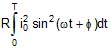 = RT
= RT 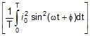 = i2rms RT
It means the root mean square value of ac is that value of steady current, which would generated the same amount of heat in a given resistance in a given time.
So in ac circuits, current and ac voltage are measured in terms of their rms values. Likes when we say that the house hold supply is 220 V ac it means the rms value is 220 V and peak value is = 311 V.
Ex.2 If the voltage in an ac circuit is represented by the equation, V = sin (314t -  ),calculate (a) peak and rms value of the voltage, (b) average voltage, (c) frequency of ac.
Sol. (a) For ac voltage,
V = V0 sin (ωt -  )
)
The peak value of voltage
V0 =  = 311 V
The rms value of voltage
(b) Average voltage in full cycle is zero. Average voltage in half cycle is
Vavg =  =
=  = 198.17 V
(c) As ω = 2πf, 2ωf = 314
i.e., f =  = 50 Hz
Ex.3 The electric current in a circuit is given by i = i0 (t/T) for some time. Calculate the rms current for the period t = 0 to t = T.
Sol. The mean square current is
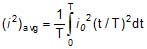 =
= 
Thus, the rms current is
irms = 
=======================================================================
Series AC Circuit - Alternating Current, Class 12, Physics
3. SERIES AC CIRCUIT
3.1 When only Resistance is in an AC circuit
Consider a simple ac circuit consisting of a resistor of resistance R and an ac generator, as shown in the figure. According to Kirchhoff's loop law at any instant, the algebraic sum of the potential difference around a closed loop in a circuit must be zero.

ε - VR = 0
ε - iRR = 0
ε0 sinωt - iRR = 0
iR =  sinωt = i0 sin ωt ..(i)
where i0 is the maximum current. i0 = 
From above equations, we see that the instantaneous voltage drop across the resistor
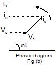
VR = i0R sinωt ...(ii)
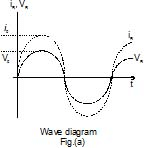
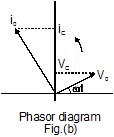
We see in equation (i) & (ii), iR and VR both vary as sin wt and reach their maximum values at the same time as shown in figure (a), they are said to be in phase. A phasor diagram is used to represent phase relationships. The lengths of the arrows correspond to V0 and i0. The projections of the arrows onto the vertical axis give VR and iR. In case of the single-loop resistive circuit, the current and voltage phasors lie along the same line, as shown in figure (b), because iR and VR are in phase.
3.2 When only Inductor is in An AC circuit
Now consider an ac circuit consisting only of an Inductor of inductance L connected to the terminals of an ac generator, as shown in the figure. The induced emf across the inductor is given by Ldi/dt. On applying Kirchhoff's loop rule to the circuit
ε- VL = 0 ⇒ ε - L
When we rearrange this equation and substitute
ε = ε0 sin ωt, we get 
 = ε0 sin ωt ...(iii)
Integration of this expression gives the current as a function of time
iL =  = -
= - 
For average value of current over one time period to be zero, C = 0
Therefore, iL = - 
When we use the trigonometric identity
coswt = - sin(wt - p/2), we can express equation as
iL =  ...(iv)
From equation (iv), we see that the current reaches its maximum values when cos wt = 1.
i0 =  =
=  ...(v)
where the quantity XL, called the inductive reactance, is
XL = ωL
The expression for the rms current is similar to equation (v), with ε0 replaced by εrms.
Inductive reactance, like resistance, has unit of ohm.
We can think of equation (v) as Ohm's law for an inductive circuit.
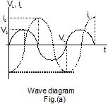
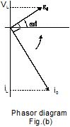
On comparing result of equation (iv) with equation (iii), we can see that the current and voltage are out of phase with each other by π/2 rad, or 90º. A plot of voltage and current versus time is given in figure (a). The voltage reaches its maximum value one quarter of an oscillation period before the current reaches its maximum value. The corresponding phasor diagram for this circuit is shown in figure (b). Thus, we see that for a sinusoidal applied voltage, the current in an inductor always lags behind the voltage across the inductor by 90º.
Ex.4 An inductor of inductance L = 5 H is connected to an
AC source having voltage v = 10 sin (10t +  )
)
Find 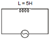
(i) Inductive Reactance (xL)
(ii) Peak & Rms voltage (V0 & Vrms)
(iii) Peak & Rms current (I0 & Irms)
(iv) Intstantatious current (I(t))
Sol. (i) xL = ωL = 10 × 5 = 50
(ii) v0 = 10
vrms = 
(iii) 
Irms = 
(iv) I(t) = 
3.3 When only Capacitor is in An AC circuit
Figure shows an ac circuit consisting of a capacitor of capacitance C connected across the terminals of an ac generator. On applying Kirchhoff's loop rule to this circuit, we get
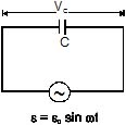
ε - VC = 0
VC = ε = ε0 sin ωt ...(vi)
where VC is the instantaneous voltage drop across the capacitor. From the definition of capacitance, VC = Q/C, and this value for VC substituted into equation gives
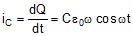
Q = C ε0 sin ωt
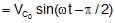
Since i = dQ/dt, on differentiating above equation gives the instantaneous current in the circuit.
Here again we see that the current is not in phase with the voltage drop across the capacitor, given by equation (vi). Using the trigonometric identity cos ωt = sin(ωt + π/2), we can express this equation in the alternative from
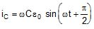 ...(vii)
From equation (vii), we see that the current in the circuit reaches its maximum value when cos ωt= 1.

Where XC is called the capacitive reactance.

The SI unit of XC is also ohm. The rms current is given by an expression similar to equation with V0 replaced by Vrms.
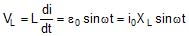
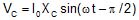
Combining equation (vi) & (vii), we can express the instantaneous voltage drop across the capacitor as
VC = V0 sin ωt = i0 XC sin ωt
Comparing the result of equation (v) with equation (vi), we see that the current is π/2 rad = 90º out of phase with the voltage across the capacitor. A plot of current and voltage versus time, shows that the current reaches its maximum value one quarter of a cycle sooner than the voltage reaches its maximum value. The corresponding phasor diagram is shown in the figure (b). Thus we see that for a sinusoidally applied emf, the current always leads the voltage across a capacitor by 90º.
Brain Teaser
What is the reactance of a capacitor connected to a constant DC source ?
Ex.5 A capacitor of capacitive reactance 5? is connected with A.C. source having voltage V = 3 sin (ωt + p/6). Find rms and Peak voltage rms and peak current and instantaneous current
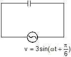
Sol. On comparing with
 ⇒ v0 = 3
 ⇒
⇒ 
 ⇒ I(t) = I0 sin
==============================================================
Series L-R, C-R and C-R Circuit - Alternating Current, Class 12, Physics
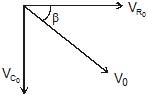
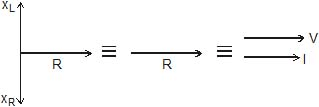
4. SERIES L-R CIRCUIT
Now consider an ac circuit consisting of a resistor of resistance R and an inductor of inductance L in series with an ac source generator.
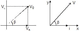
Suppose in phasor diagram, current is taken along positive x-direction. The VR is also along positive x-direction and VL along positive y-direction as we know that potential difference across a resistance in ac is in phase with current and it leads in phase by 90º with current across the inductor, and as we know VR = i0R & V0 = i0XL
i = i0 sin wt 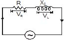
VR(t) = i0 Rsin ωt
VL(t) = i0 XL sin (ωt + p/2)
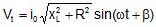
hence we can write
V(t) = i0R sin ωt + i0 XL sin (ωt + p/2)
V0 = i0
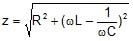
where  is known as impedence (z) of the circuit.
now we can write
where tan β= 
hence β = 
Ex.6 When 100 volt dc is applied across a coil, a current of 1 amp flows through it; when 100 V ac of 50 Hz is applied to the same coil, only 0.5 amp flows. Calculate the resistance of inductance of the coil.
Sol. In case of a coil, i.e., L - R circuit.
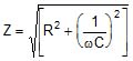
i =  with Z =
  =
= 
So when dc is applied, ω = 0, so z = R
and hence i =  i.e., R =
  =
=  = 200 ?
 i.e., ω2L2 = Z2-R2
i.e., (2πfL)2 = 2002 - 1002 = 3 × 10⁴ (as ω = 2πf)
So, L =  =
=  = 0.55 H
Ex.7 A 12 ohm resistance and an inductance of 0.05/p henry with negligible resistance are connected in series. Across the end of this circuit is connected a 130 volt alternating voltage of frequency 50 cycles/second. Calculate the alternating current in the circuit and potential difference across the resistance and that across the inductance.
Sol. The impedance of the circuit is given by
Z =  =
= 
=  =
=  = 13 ohm
Current in the circuit i = E/Z =  = 10 amp
Potential difference across resistance
VR = iR = 10 × 12 = 120 volt
Inductive reactance of coil XL = ωL = 2πfL
Therefore, XL = 2π × 50 ×  = 5 ohm
Potential difference across inductance
VL = i × XL = 10 × 5 = 50 volt
5. SERIES C-R CIRCUIT
Now consider an ac circuit consisting of a resistor of resistance R and an capacitor of capacitance C in series with an ac source generator.
Suppose in phasor diagram current is taken along positive x-direction. Then VR is also along positive x-direction but VC is along negative y-direction as potential difference across a capacitor in ac lags in phase by 90º with the current in the circuit. So we can write,
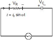
VR = I0 R sin ωt 
Potential difference across capacitor
Potential at any instant t

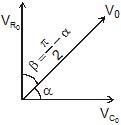
V(t) = V0 sin (ωt + b)
tan α = 
Ex.8 An A.C. source of angular frequency w is fed across a resistor R and a capacitor C in series. The current registered is i. If now the frequency of the source is changed to ω/3 (but maintaining the same voltage), the current in the circuit is found to be halved. Calculate the ratio of reactance to resistance at the original frequency.
Sol. At angular frequency w, the current in R-C circuit is given by
irms = 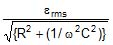 ...(i)
When frequency is changed to ω/3, the current is halved. Thus
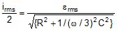 =
=  ...(ii)
...(ii)
From equations (i) and (ii), we have
 =
= 
Solving this equation, we get 
Hence, the ratio of reactance to resistance is 
Ex.9 A 50 W, 100 V lamp is to be connected to an ac mains of 200 V, 50 Hz. What capacitance is essential to be put in series with the lamp?
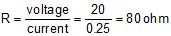
Sol. As resistance of the lamp R =  = 200 ? and the maximum current i =
  =
=  =
=  ; so when the lamp is put in series with a capacitance and run at 200 V ac, from V =iZ we have,
Z =  =
=  = 400?
Now as in case of C-R circuit, Z =  ,
,
i.e., R2 +  = 160000
or,  = 16 × 104 - (200)2 = 12 × 104
So,  =
=  × 102
× 102
or C = 
i.e., C =  = 9.2 μF
5. L.C. circuit
As shown in figure a capacitor and inductance are connected in series method and alternating voltage is applied across the circuit.
Let Xc is capacitance reactance,
XL is Inductance reactance,
i = i0 sin wt current floing through the circuit
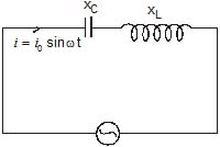
VC(t) = i0 XC sin (ωt - π/2)
VL(t) = i0 XL sin (ωt + π/2)

= i0 XC sin wt cos π/2 - i0 XC cos wt sin π/2 + i0 XL sin wt cos π/2 + i0 XL cos wt sin π/2
= i0 cos w t(XL - XC)
V(t) = V0sin (wt + p/2)
V0 = i0Z 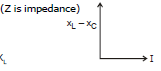
Z = (XL - XC)
cos  = 0
= 0
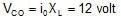
VCO = i0 XC ; 
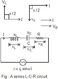
6. SERIES L-C-R CIRCUIT
Now consider an ac circuit consisting of a resistor of resistance R, a capacitor of capacitance C and an inductor of inductance L are in series with an ac source generator.
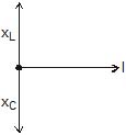
Suppose in a phasor diagram current is taken along positive x-direction. Then VR is along positive x-direction, VL along positive y-direction and VC along negative y-direction, as potential difference across an inductor leads the current by 90° in phase while that across a capacitor, lags by 90°.
V = 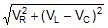
L - R - C circuit
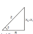
Impedance phasor of above circuit
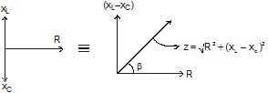
& Impedance triangle
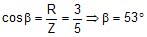
here B is phase angle By triangle tan β= 
Power factor cos =
= 
Let I be the current in the series circuit of any instant then
(1) Voltage V(t) = V0 sin (ωt + β) = i0 z sin (ωt + β)
here v0 = i0z & vrms = irmsz
(2)  here voltage VL across the inducetance is ahead of current I in phase by π/2 rad

(3) VC(t) = VO C sin (ωt - π/2)
here voltage VC across the capacitance lags behind the current I in pase by π/2 rad

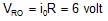
(4) VR(t) = i0 R sin ωt
here voltage VR across the resistor R has same phase as I
VO R = IO R
Special Case :
(1) When XL > XC or VL > VC then emf is ahead of current by phase β which is given by
tan β =  or cos f =
The series LCR circuit is said to be inductive
(2) When XL < XC or VL < VC then current is ahead of emf by phase angle β which is given by
 or
or 
The series LCR circuit is said to be capacitive
(3) When XL = XC or VL = VC, b = 0, the emf and current will be in the same phase. The series LCR circuit is said to be purely resistive. It may malso be noted that
 or
or  or IRms =
Susceptance : The reciprocal of the reactane of an a.c. circuit is called its susceptance.
Admittance : The reciprocal of the impedance of an a.c. circuit is called its admittance.
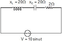
Ex.10 Figure shows a series LCR cicuit connected to a variable voltage source V = 10 sin (ωt + p/4) ;
xL = 10 ?, XC = 6 ?, R = 3 ?
Calculate Z, i0, irms, vrms, VL O, VC O, VR O, b,
VL Rms, VC Rms, VRms, i(t), VL(t), Vc(t), and VR(t)
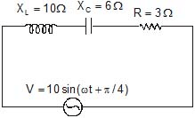 XL > XC
Sol. V = 10 sin (wt + p/4) so V0 = 10 volt
Vrms = 
Therefore, Z = 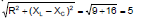


 ;
; 
 ;
; 
 ;
; 
i(t) = 20 sin (ωt + π/4 - 53°)
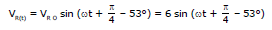
VL(t) = 20 sin (ωt + π/4 - 53° + π/2)
= 20 sin (ωt +  - 53° -
  ) = 12 sin (ωt -
  - 53°)
Ex.11 A resistor of resistance R, an inductor of inductance L and a capacitor of capacitance C all are connected in series with an a.c. supply. The resistance of R is 16 ohm and for a given frequency the inductive reactance of L is 24 ohm and capacitive reactance of C is 12 ohm. If the current in the circuit is 5 amp., find
(a) the potential difference across R, L and C (b) the impedance of the circuit
(c) the voltage of a.c. supply (d) phase angle
Sol. (a) Potential difference across resistance
VR = iR = 5 × 16 = 80 volt
Potential difference across inductance
VL = i × (wL) = 5 × 24 = 120 volt
Potential difference across condenser
VC = i × (1/wC) = 5 × 12 = 60 volt
(b)  =
= =20 ohm
(c) The voltage of a.c. supply is given by
V = iZ = 5 × 20 = 100 volt
(d) Phase angle
 =
=  =
= 
= tan-1(0.75) = 36°87'
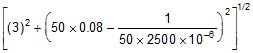
Ex.12 A series circuit consists of a resistance of 15 ohm, an inductance of 0.08 henry and a condenser of capacity 30 micro farad. The applied voltage has a frequency of 500 radian/s. Does the current lead or lag the applied voltage and by what angle?
Sol. Here ωL = 500 × 0.08 = 40 ohm
and 
= 66.7 ohm
tan =
= 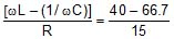 = - 1.78
 = - 60.67°
Thus the current leads the applied voltage by 60.67°
Ex.13 A current of 4 A flows in a coil when connected to a 12 V d.c. source. If the same coil is connected to a 12 V, 50 rad/s, a.c. source, a current of 2.4 A flows in the circuit. Determine the inductance of the coil. Also find the power developed in the circuit if a 2500 μF condenser is connected in series with the coil.
Sol. When the coil is connected to a d.c. source, its resistance R is given by
R =  =
=  = 3 ?
= 3 ?
When it is connected to a.c. source, the impedance Z of the coil is given by
Z =  =
=  = 5?
= 5?
For a coil, Z = 
Therefore, 5 = 
or 25 = [(3)2 + (50L)2]
Solving we get L = 0.08 henry
When the coil is connected with a condenser in series, the impedance Z' is given by
Z' =  =
= 
= 5 ohm
Power developed P = Vrms × irms × cosf
where cos  = R/Z' = 3/5 = 0.6
Therefore, P = 12 × 2.4 × 0.6 = 17.28 watt
Ex.14 A 20 volts 5 watt lamp is used in ac main of 220 volts 50 c.p.s. Calculate the (i) Capacitance of capacitor. (ii) Inductance of inductor, to be put in series to run the lamp, (iii) What pure resistance should be included in place of the above device so that the lamp can run on its voltage. (iv) Which of the above arrangements will be more economical and why ?
Sol. The current required by the lamp
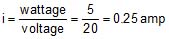
The resistance of the lamp
So for proper running of the lamp, the current through the lamp should be 0.25 amp
(i) When the condenser C is placed in series with lamp, then
The current through the circuit
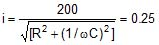 or
or 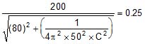
Solving it for C, we get
C = 4.0 × 10⁻⁶ F = 4.0 μF
(ii) When inductor L henry is placed in series with the lamp, then
 or
or 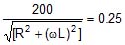
or 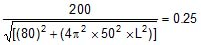
Solving it for L, we get L = 2.53 henry
(iii) When resistance r ohm is placed in series with lamp of resistance R, then

or 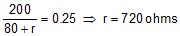
(iv) It will be more economical to use inductance or capacitance is series with the lamp to run it as it consumes no power while there would be dissipation of power when resistance is inserted in series with the lamp.
Brain Teaser
Can the peak voltage across the inductor be greater than the peak voltage of the source in an LCR circuit ?
Power in AC Circuit - Alternating Current, Class 12, Physics
7. Power in an AC circuit
In case of a steady current the rate of doing work is given by,
P = Vi
In an alternating circuit, current and voltage both vary with time, so the work done by the source in time interval dt is given by
dW= Vidt
Suppose in an ac, the current is leading the voltage by an angle . Then we can write,
V = V0 sinωt
and i = i0 sin(ωt + )
)
dW = V0i0 sin ωt sin (ωt +  ) dt
) dt
= V0 i0 (sin2 ωt cos f + sinωt cos ωt sin ) dt
) dt
The total work done in a complete cycle is
W = V0i0 cos
 + V0i0sin
 +
+  =
= 
The average power delivered by the source is, therefore,
P =  =
=  =
= 
= Vrms irms cos
or <P>one cycle = Vrms irms cos
Here, the term cos  is known as power factor.
It is said to be leading if current leads voltage, lagging if current lags voltage. Thus, a power factor of 0.5 lagging means current lags the voltage by 60° (as cos-10.5 = 60°). The product of Vrms and irms gives the apparent power. While the true power is obtained by multiplying the apparent power by the power factor cos . Thus,
and apparent power = Vrms × irms
True power = apparent power × power factor
For  = 0°, the current and voltage are in phase. The power is thus, maximum (Vrms× irms). For
 = 90°, the power is zero. The current is then stated as wattless. Such a case will arise when resistance in the circuit is zero. The circuit is purely inductive or capacitive.
==============================================
Resonance - Alternating Current, Class 12, Physics
8. Resonant Frequency
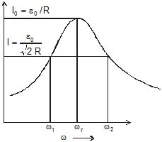
A series LCR circuit is said to be in the resonance condition when the current through it has its maximum value.
The current amplitude I0 for a series LCR circuit is given by
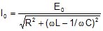
Clearly I0 becomes zero both for ω → 0 and ω → ∞. The value of I0 is maximum when
 or
or 
⇒ 
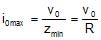
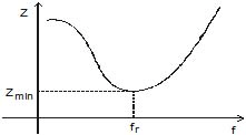
Then impedance will be minimum
Zmin = R
The circuit is purely resistive. The current and voltage are in the same phase and the current in the circuit is maximum. This condition of the LCR circuit is called resonance condition. 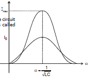
The variance of I0 v/s ω shown in following figure
So cos  =
=  =
=  = 1
= 1
V = V0 sin (ωt)
Impedance phase of resonance circuit
Impedance of the circuit is minimum and heat generated in the circuit is maximum.
Ex.15 In following LCR circuit find Z, i(t), VOC, VOL at resonace frequency
Sol. Z = Zmin = R = 2?
VO L = i0XC = 100 volt
VO L = i0 XL = 100 volt
 : Above circuit is used as voltage amplifier (magnification) as peak value of voltage by source is only 10 while we can have maximum voltage up to 100 (VO C& VO L)
Ex.16 A series LCR with R = 20 ?, L = 1.5 H and C = 35 μF is connected to a variable frequency 200 V a.c. supply. When the frequency of the supply equals the natural frequency of the circuit. What is the average power transferred to the circuit in one complete cycle?
Sol. When the frequency of the supply equals the natural frequency of the circuit, resonance occurs.
Therefore, Z = R = 20 ohm
irms = 
Average power transferred/cycle
P = Ermsirms cos0° = 200 × 10 × 1 = 2000 watt
8.1 Sharpness of Resonance (Q - factor) :
The Q- factor of a series resonant circuit is defined as the ratio of the resonant frequency to the difference in two frequencies taken on the both sides of the resonant frequency such that at each frequency, the current amplitude becomes  times the value of resonant frequency.
Mathematically Q-factor.
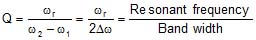
or 
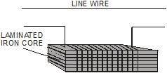
9. Choke Coil :
A choke coil is simply an inductor with large inductance which is used to reduce current in a.c. circuit without much loss of energy.
Principle. A choke coil is based upon the principle that when a.c. flows through an inductor, the current lags behind the e.m.f. by a phase angle π/2.
Construction. A choke coil is basically an inductance. It consists of a large number of turns of insulated copper wire wound over a soft iron core. In order to minimise loss of electrical energy due to production of eddy currents, a laminated iron core is used.
In practice, a low frequency choke coil is made of insulated copper wire wound on a soft iron core, while a high frequnecy choke coil has air as core materials
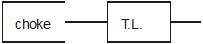
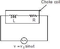
Working : As shown in fig a choke is put in series across an electrical appliances of resistance R and is connected to an a.c. source.
Average power dissipiated per cycle in the circuit is
Pav = Veff Ieff cosf = Veff Ieff  .
.
Inductance L of the choke coil is very large so that R << wL. Then
Power factor cos


 0
0 
tan =
= 
Uses. In a.c. circuit, a choke coil is used to control the current in place of a resistance. If a resistance is used to control the current, the electrical energy will be wasted in the form of heat. A choke coil decreases the current without wasting electrical energy in the form of heat.
10. OSCILLATIONS IN L-C CIRCUIT
If a charged capacitor C is short-circuited through an inductor L, the charge and current in the circuit start oscillating simple harmonically. If the resistance of the circuit is zero, no energy is dissipated as heat. Assume an ideal situation in which energy is not radiated away from the circuit. With these idealizations-zero resistance and no radiation, the oscillations in the circuit persist indefinitely and the energy is transferred from capacitor's electric field to the inductor's magnetic field back and forth. The total energy associated with the circuit is constant. This is analogous to the transfer of energy in an oscillating mechanical system from potential energy to kinetic energy and back, with constant total energy. Such an analogous mechanical system is an example of spring mass system.
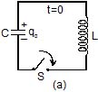
Let us now derive an equation for the oscillations of charge and current in an L-C circuit. Refer figure (a) : The capacitor is charged to a potential difference V such that charge on capacitor q0 = CV
Here q0 is the maximum charge on the capacitor. At time t = 0, it is connected to an inductor through a switch S. At time t = 0, the switch S is closed.
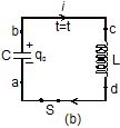
Refer figure (b) : When the switch is closed, the capacitor starts discharging. Let at time t charge on the capacitor is q (<q0) and since, it is further decreasing, there is a current i in the circuit in the direction shown in figure.
The potential difference across capacitor = potential difference across inductor, or
Vb - Va = Vc - Vd
Therefore,  ...(1)
Now, as the charge is decreasing, i = 
or  = -
= - 
Substituting in equation (1), we get

or  = -
= -  ...(2)
This is the standard equation of simple harmonic motion 
Here w =  ...(3)
The general solution of equation (2), is
q = q0 cos (ωt ±  ) ...(4)
In our case  = 0 as q = q0 at t = 0.
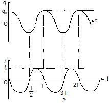
Thus, we can say that the charge in the circuit oscillates with angular frequency ω given by equation (3). Thus,
ln L - C oscillations, q, i and  all oscillate simple harmonically with same angular frequency ω, but the phase difference between q and i or between i and
  is . Their amplitudes are q0 q0ω are ω2 q0 respectively. So
q = q0 cosωt, then ...(5)
i = - = q0ω sin ωt ...(6)
and  cosωt ...(7)
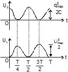
Potential energy in the capacitor
UC =  =
=  ...(8)
Potential energy in the inductor
UL =  =
=  ...(9)
Thus potential energy stored in the capacitor and that in the inductor also oscillates between maximum value and zero with double the frequency. All these quantities are shown in the figures that follows
Ex.17 A capacitor of capacitance 25 μF is charged to 300 v. It is then connected across a 10 μH inductor. The resistance of the circuit is negligible.
(a) Find the frequency of oscillation of the circuit.
(b) Find the potential difference across capacitor and magnitude of circuit current 1.2 ms after the inductor and capacitor are connected.
(c) Find the magnetic energy and electric energy at t = 0 and t = 1.2 ms.
Sol. (a) The frequency of oscillation of the circuit is ,
f = 
Substituting the given values we have, 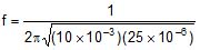 =
= 
(b) Charge across the capacitor at time t will be ,
q = q0 cos ωt
and i = - q0 ωsin ωt
Here q0 = CV0 = (25 × 10-6) (300) = 7.5 × 10⁻³ C
Now, charge is the capacitor after t = 1.2 × 10⁻³ s is,
q = (7.5 × 10⁻³) cos (2p × 318.3) (1.2 × 10⁻³)C
= 5.53 × 10⁻³C
Therefore, P.D. across capacitor,
V = 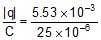 = 221.2 volt
The magnitude of current in the circuit at
t = 1.2 × 10⁻³ s is,
|i| = q0 ω sinωt
= (7.5 × 10⁻³) (2p) (318.3) sin(2p × 318.3) (1.2 × 10⁻³) A = 10.13 A
(c) At t = 0 : Current in the circuit is zero. Hence,UL = 0
Charge on the capacitor is maximum
Hence, Uc = 
or Uc = 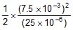 = 1.125 J
Therefore, Total energy E = UL + UC = 1.125 J
At t = 1.2 ms
UL =  =
=  (10.13)2 = 0.513 J
UC = E - UL = 1.125 - 0.513 = 0.612 J
Otherwise UC can be calculated as,
UC =  =
=  = 0.612 J
====================================================================
Transformers - Alternating Current, Class 12, Physics
11. Transformer :
A transformer is an electrical device for converting an alternating current at low voltage into that at high voltage or vice versa. If it increase the input voltage, it is called step up transformer and if it decreases the input voltage, it is called step down transformer.
Principle : It works on the principle of mutual induction, i.e., when a changing current is passed through one of the two inductively coupled coils, an induced emf is setup in the other coil.
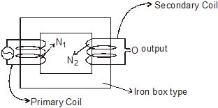
Construction : A transformer essentially consists of two coils of insulated copper wire having different number of turns and wound on the same soft iron core. The coil to which electric energy is supplied is called the primary and the coil from which energy is drawn or output is obtained is called the secondary.
To prevent energy losses due to eddy currents, a laminated sheet is used. Because of high permeability of soft iron, the entire magnetic flux due to the current in the primary coil practically remains in the iron core and hence passes fully through the secondary.
Two types of arrangements are generally used for winding of primary and secondary coils in a transformer.
1. Core type : In this type, the primary and secondary coils are wound on seperate limbs of the core.
2. Shell type : In this type the primary and secondary coils are wound one over another on the same limb of the iron core.
Theory : Consider the situation when no load is connected to the secondary, i.e., its terminals are open. Let N1 and N2 be the number of terminal in the primary and secondary respectively. Then Induced emf in the primary coil

Induced emf in the secondary coil

where is the magnetic flux linked with each turn of the primary or secondary at any instant. Thus

The ratio  of the number of turns in the secondary to that in the primary called the turns ratio of the transformer. It is also called transformation ratio
for step up transformer : N2 > N1
for step down transformer : N1 > N2
Currents in primary and secondary : Assuming the transformer to be ideal one so that there are no energy loss, then
Input power = output power
or Vp Ip = Vs Is
where Ip and IS are the currents in the primary and secondary respectively.
Hence 
Efficiency : The efficiency of a transformer is defined as
η =  × 100%
The efficiency of real transformer is fairely high (90 - 98%) though not 100%
Extra Portion For IIT-Mains
Explain with the help of a labelled diagram, the principle and working of an a.c. generator ? Write the expression for the emf generated in the coil in terms of speed of rotation. Can the current produced by an a.c. generator be measured with a moving coil galvanometer.
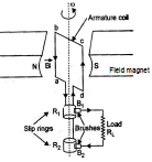
Sol. AC generator : A dynamo or generator is a device which converts mechancial energy into electrical energy. It is based on the principle of electromagnetic induction.
Construction : It consists of the four main parts :
(i) Field Magnet : It produces the magnetic field. In the case of a low power dynamo, the magnetic field is generated by a permanent magnet, while in the case of large power dynamo, the magnetic field is produced by an electromagnet.
(ii) Armature : It consists of a large number of turns of insultated wire in the soft iron drum or ring. It can revolve reound an axle between the two poles of the field magnet. The drum or ring serves the two purposes : (i) It serves as a support to coils and (ii) It increases the magnetic field due to air core being replaced by an iron core :
(iii) Slip Rings : The slip rings R1 and R2 are the two metal rings to which the ends of armature coil are connected. These rings are fixed to the shaft which rotates the armature coil so that the rings also rotate along with the armature.
(iv) Brushes : These are two flexible metal plates or carbon rods (B1 and B2) which are are fixed and constantly touch the revolving rings. The ouput current in extyernal load RL is taken through these brushes.
Working : When the armature coil is rotated in the strong magnetic field, the magnetic flux linked with the coil changes and the current is induced in the coil, its direction being given by Fleming's right hand rule. Considering the armature to be in vertical positoin and as it rotates
in anticlockwise direction, the wire ab moves upward and cd downward, so that the direction of induced current is shown in fig. In the external circuit, the current flows along B1 BL B2. The direction of current remains unchanged during the first half turn of armature. During the second half revolution, the wire ab moves downward and cd upward, so the direction of current is reversed and in external circuit if flows along B2 RL B1. Thus the direction of induced emf and current changes in the external circuit after each half revolution.
If N is the number of turns in coil, f the frequency of rotation. A area of coil and B the magnetic induction, then induced emf
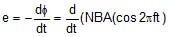
Obviously, the emf produced is alternating and hence the current is also alternating
Current produced by an ac generator cannot be measured by moving coil ammeter, because the average value of ac over fully cycle is zero.
FAQs on Alternating Current, Class 12, Chapter Notes, Physics (IIT - JEE & AIPMT)
| 1. What is an alternating current? |  |
| 2. What is the difference between AC and DC? | |
| 3. What is the frequency of AC in India? | |
| 4. What is the RMS value of AC? | |
| 5. What is the advantage of using AC over DC? | |


