AC Bridges - 1 | Electrical Engineering SSC JE (Technical) - Electrical Engineering (EE) PDF Download

What are AC Bridges?
The “AC Bridge” is a natural outgrowth of the DC bridge (Wheatstone bridge) in its basic form consisting of Four bridge arms, a source of excitation, and a null or balanced detector.
These bridge methods are very useful for the measurement of:
- Inductance (L)
- Capacitance (C)
- Frequency (f)
- Mutual inductance (M)
- Storage factor
- Loss factor, etc.
Types of Sources in AC Bridges
- For Low frequency measurement the power line supply can serve as the source of excitation.
- For High frequency measurement the electronic oscillator is used as excitation voltage.
Types of Detectors in AC Bridges
1. Headphones
- It is used at frequencies of 250 Hz and over upto 3 to 4 KHz.
- Most sensitive detector for this ranges of frequency.
2. Vibration Galvanometer
- It can be used from 5 Hz to 1000 Hz but suitable mainly upto 200 Hz.
- They are extremely useful for power and low AF ranges.
3. Tuneable Amplifier Detector (TAD)
- It can be used at 10 Hz to 100 KHz.
4. Cathode Ray Oscilloscope (CRO)
- It is used for higher frequencies more than 5 KHz.
Note: For a DC Bridge , the PMMC(Permanent Magnet Moving Coil) instrument acts as a detector.
AC Bridges through which Inductance (L) is Measured
1. Maxwell’s Inductance Bridge
This bridge measures an unknown inductance by comparison with a variable standard self-inductance.
 Maxwell's Inductance Bridge
Let R1 and L1 be unknown quantities.
L2 = Variable inductance of fixed resistance ‘r2’
R2 = Variable resistance connected in series with “L2”
R3 and R4 = Known non-inductive resistances.
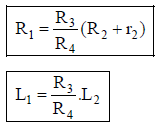
At balance condition,
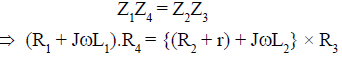
equating real and imaginary parts we get,
2. Maxwell’s Inductance-Capacitance Bridge
This Bridge measures an unknown inductance in terms of a known capacitance.
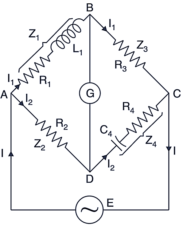
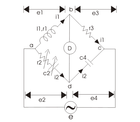
 Maxwell Inductance Capacitance Bridge
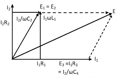
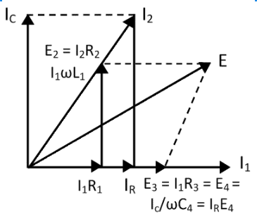 Phasor Diagram for Maxwell Inductance Capacitance Bridge
Let R1 and L1 are unknown quantity R2, R3 and R4 are known non-inductive resistances and C4 = variable standard capacitor
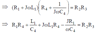
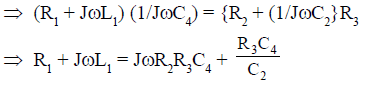
At balance condition, Z1Z4 = Z2Z3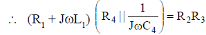
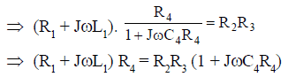
Equating the real part we get,

and equating the imaginary part we get,
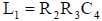
Quality Factor: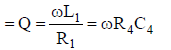
Advantages:
- Circuit is simple.
- Obtained balance equations are free from the frequency term.
- Balance equations are independent if we choose R4 and C4 as variable elements.
- It is very useful for measurement of a wise range of inductances at power and audio frequencies.
Disadvantages:
- It requires a variable standard capacitor which is very costly.
- The bridge is limited to the measurement of low-quality coils (1 < Q < 10) and it is also unsuitable for the low value of Q (i.e. Q < 1) from this we conclude that a Maxwell bridge is suitable only for medium Q coils.Question for AC Bridges - 1Try yourself:Which of the following statements is true regarding the Maxwell’s Inductance-Capacitance Bridge?
View Solution
3. HAY’s Bridge
It is a modification of Maxwell’s bridge.- This bridge uses resistances in series with the standard capacitor as shown in figure below,
 Hay's Bridge
 Phasor Diagram of Hay's Bridge
Let,R1 and L1 are unknown quantity
R2, R3 and R4 are non-inductive resistances.
and C4 = standard capacitor
At balance condition,
Z1Z4 = Z2Z3
Equating real and imaginary parts we get, 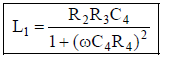 and
and 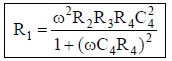
Quality factor = 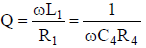
i.e.  Now
Now 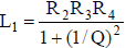 and
and 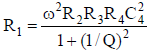
- In this bridge, the expression for the unknown inductance and resistance involves the frequency term.
So, for the higher Q (i.e. Q > 10) 1 + (1/Q)2 ≈ 1 and then,
- So, we can say this bridge is suitable for high Q-coils (i.e. Q > 10)
Advantages:
- It gives a simple expression for the Q-factor.
- For high Q-coils, it gives a simple expression for unknown R1 and L1.
Disadvantages:
- It is not suitable for medium or low Q-coils.
4. Anderson’s Bridge
- It is a modification of the Maxwell’s inductance-capacitance bridge.
- In this bridge method, the self-inductance is measured in terms of standard capacitor
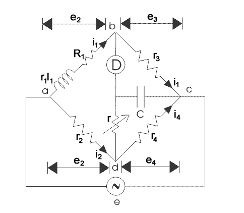 Anderson's Bridge
At balanced condition, Vb = Ve
So, ID = 0
Also for the Delta network
we can convert this in star form
as 
So,
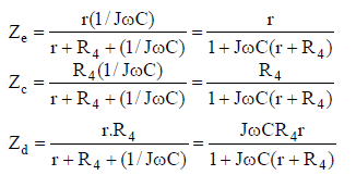 For balance condition, Zab.Zc = ZaN.Zbc
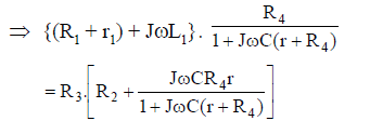
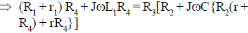
Equating the real part we get,
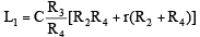
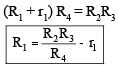 Now equating the imaginary part we get,
L1 R4 = R3C[R2 R4 + rR2 + rR4]
Phasor diagram for Anderson’s bridge:
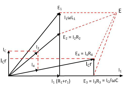 Phasor Diagram for Anderson's Bridge
Quality factor = 
- It is suitable for Low Q-coils (i.e. Q < 1).
Advantages:
- It may be used for accurate estimation of capacitance in terms of inductance.
- It is relatively cheaper because here fixed capacitance is used.
- It is much easier to obtain the balance.
Disadvantage:
- It is a more complex circuit.
- The balance equations are not simple and are much more tedious.
- An additional junction point increases the difficulty of shielding the bridge network.
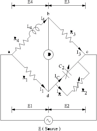
5. Owen’s Bridge
- This bridge may also be used for the measurement of inductance in terms of capacitance.
 Owen's Bridge
 Phasor Diagram for Owen's Bridge
Let R1 and L1 be the unknown quantity
R2 = Variable non-inductive resistance
R3 = Fixed non-inductive resistance
C2 = Variable standard capacitor
C4 = Fixed standard capacitor
At balance condition,
ZabZcd = Zad. Zbc
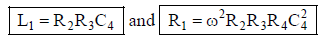
Equating real and imaginary parts we get,
and
L1 = R2 R3 C4
Quality factor = 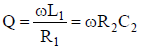
Advantages:
- It has independent balance equations.
- The unknown quantities expressions are free from frequency terms.
This can be used over a wide range of measurements of inductances.
Disadvantages:
- It requires a variable capacitor so it is a very costly network.
- Its accuracy is about only 1%.
AC bridges through which capacitances are measured
1. De Sauty’s Bridge
- It is the simplest method of comparing two capacitances.
- It may also be used for determining the dissipation factor (D).
Considering ideal capacitors, the bridge circuit is,
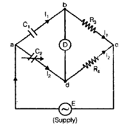 De Sauty BridgeLet C1 = unknown capacitor
C2 = a standard capacitor
R3 and R4 = non-inductive resistors
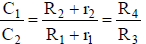
At balance condition:
Zab . Zcd = Zad . Zbc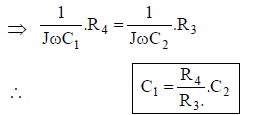
The advantage of this bridge is its simplicity but from this we can not determine the “Dissipation Factor (D)”, so some modifications are needed in the above bridge.
Now we consider the lossy capacitor and bridge to become “Modified De-Sauty’s Bridge”.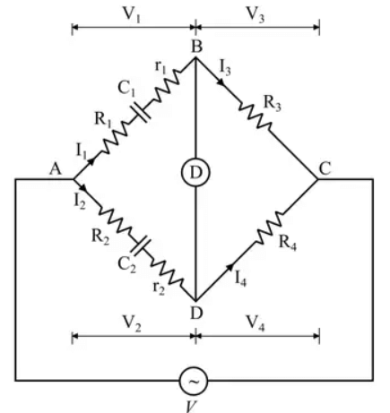 Modified De Sauty Bridge
- Given C2 so, D2 = ωC2r2 and we have to estimate C1 and hence D1 = ωC1r1
At balance condition,
Zab . Zcd = Zbc . Zad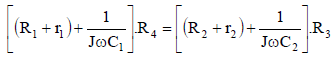
Equating real part we get, (R1 + r1)R4 = (R2 + r2)R3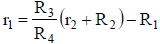 Now equating the imaginary part we have,
 and
and 
Also,
- This bridge can not determine the accurate result for the dissipation factor because we have,
D 2 – D1 = ω[C2r2 – C1r1]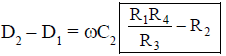
Since (D2 – D1) is very- very small it is difficult to determine “D1” accurately.
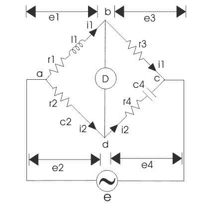
2. Schering Bridge
The Schering bridge is used for measuring the capacitance of the capacitor, dissipation factor, properties of an insulator, capacitor bushing, insulating oil, and other insulating materials. It is one of the most commonly used AC bridges. The Schering bridge works on the principle of balancing the load on its arm.
In this diagram: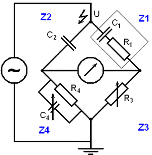 Schering Bridge
- C1 = capacitor whose capacitance is to be determined
- R1 = a series resistance representing the loss in the capacitor C1
- C2 = a standard capacitor
- R3 = a variable non-inductive resistance
- C4 = a variable capacitor
- R4 = a non-inductive resistance in parallel with the variable capacitor C4
When the bridge is in the balanced condition, zero current passes through the detector, which shows that the potential across the detector is zero. At balance condition
Z1/Z2 = Z3/Z4
Z1Z4 = Z2Z3
Substituting the values of z1, z2, z3 and z4 in the above equation, we get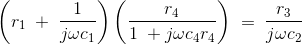
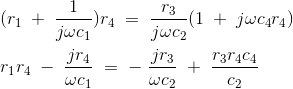
Equating the real and imaginary parts and the separating we get,

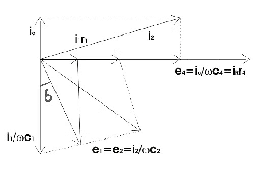 Phasor Diagram for Schering Bridge
Let us consider the phasor diagram of the above Schering bridge circuit and mark the voltage drops across ab, bc, cd, and ad as e1, e3,e4, and e2 respectively. From the above Schering bridge phasor diagram, we can calculate the value of tanδ which is also called the dissipation factor.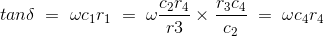
The equation that we have derived above is quite simple and the dissipation factor can be calculated easily.
Advantages of Schering Bridge:
1. Balance equations are free from frequency.
2. The arrangement of the bridge is less costly as compared to the other bridges.
|
23 videos|94 docs|42 tests
|
FAQs on AC Bridges - 1 - Electrical Engineering SSC JE (Technical) - Electrical Engineering (EE)
| 1. How do AC bridges measure inductance? |  |
| 2. What components are typically used in AC bridges to measure capacitance? | |
| 3. How does an AC bridge work in measuring inductance? | |
| 4. What is the significance of balancing an AC bridge circuit in measuring capacitance? | |
| 5. How can AC bridges be used to measure inductance and capacitance simultaneously? | |


Viva Questions
,AC Bridges - 1 | Electrical Engineering SSC JE (Technical) - Electrical Engineering (EE)
,Semester Notes
,Exam
,past year papers
,practice quizzes
,mock tests for examination
,video lectures
,Important questions
,Free
,AC Bridges - 1 | Electrical Engineering SSC JE (Technical) - Electrical Engineering (EE)
,ppt
,study material
,Sample Paper
,Summary
,shortcuts and tricks
,Extra Questions
,AC Bridges - 1 | Electrical Engineering SSC JE (Technical) - Electrical Engineering (EE)
,Previous Year Questions with Solutions
,MCQs
,Objective type Questions
,


AC Bridges - 1 Free PDF Download
Importance of AC Bridges - 1
AC Bridges - 1 Notes
AC Bridges - 1 Electrical Engineering (EE) Questions
Study AC Bridges - 1 on the App
|
© EduRev
|
Education Revolution
|


|


within 7 days!