Metal Casting - 1 | Mechanical Engineering SSC JE (Technical) PDF Download

Introduction
- Metal casting is one of the most ancient techniques used for manufacturing metal parts, Metal casting is the process of forming metallic objects by melting metal, pouring it into the shaped cavity of a mold and allowing it to solidify.
- The process of casting involves the basic operations of:

Manufacturing Process
- It is a process of converting raw material into a finished product.
- It is a process of value addition to raw material such that final product has more value in the market.
Fundamental Nature of Manufacturing Processes
Manufacturing process can be termed as positive, negative and or zero processes.
- Casting & Forming - Zero process
- Machining - Negative process
- Joining (welding) - Positive process
This grouping is based on the way bulk materials processed for final product.
Why Many Manufacturing Processes?
A wide range of manufacturing processes have been developed in order to produce the engineering component of:
Different Geometries: Simple to Complex.
Using materials of different:
- Physical Properties: Melting, Thermal expansion
- Chemical: Oxidation, Corrosion
- Mechanical: Strength, Ductility
- Dimensional Properties: tolerance, size.
Which Process to Use?
Selection of manufacturing process is decided by:
- Complexity of Geometry
- No. of units to be produced.
- Properties of the material (Physical, chemical, mechanical, Properties) to be used.
- Dimensional properties desired.
(a) Zero Process
- Casting and forming involve mainly shaping of metal in controlled way with the help cavity or die.
(b) Negative Process
- Machining is considered as a Negative process because unwanted material is removed from the stock in the form of small chips to get the desired size and shape.
Example: All machining Operation and Surface finishing operation.
(c) Positive Process
- It is used for assembling different members to get the desired shape.
Example: All welding Processes, soldering, Brazing etc.
Metal Casting
- Casting is the oldest and still most widely used process. A mould cavity is created of sand or some permanent material and liquid metal is poured into this cavity.
- The product is taken out after solidification. If the mould or pattern is broken after each cast than it is called expendable mould or pattern. If the same mould is used for a
number of casting it is called reusable mould/ pattern. - The pattern is the replica of the part being produced from the liquid metal.
- The material undergoes following shrinkages from the pouring temperature of the liquid metal to the room temperature.
1. Liquid from the pouring temperature to liquid at the melting point.
2. Shrinkage during phase change
3. Solid at melting point to solid at room temperature. - First two stages shrinkage are compensate by providing a riser.
- The riser design should be such that it solidify after casting so that liquid metal is available to compensate liquid shrinkage.
- Third stage of shrinkage is compensated by providing allowance on the pattern.
- The casting process is capable of producing intricate shapes in one piece, including those with internal cavity, such as engine blocks. A wide variety of products can be cast.
- Many casting process have been developed over many years. As in all manufacturing, each process has its own characteristics, application, advantages, limitations and costs.
- Casting processes are most often selected over other manufacturing methods for the following reasons:
(a) Casting can produce complex shapes with internal cavities or hollow sections.
(b) It can produces very large parts.
(c) Any type of material like brittle and ductile, or hard 4 soft can be casted.
Types of Allowance
(a) Shrinkage/Contraction Allowance
- To compensate the first stage of shrinkage.
- Liquid and solidification shrinkage can be compensated by providing the riser.
- These are expressed as % of shrinkage volume of the material.


- Solid shrinkage can be compensated by increasing the size of the pattern in the form of shrinkage allowance. These values are expressed in terms of linear dimensions.
(b) Machine/Finish Allowance
- Casting produces poor surface finish and tolerance. So some margin is given to the pattern for machining the parts produced after solidification.
- The machining or finishing allowance is provided on the pattern in order to remove some amount of material after the casting has been produce in order to get smooth surface finish.
(c) Draft/Taper Allowance
- Around 1/2 to 2º (shown in Figure ) taper is provided over the pattern for easy removal of pattern from the sand mould.

- Draft or Taper allowance provided for easy removal of pattern without damaging
mould
X = h tanq - Internal surface require more taper when compared to external surfaces because for the external surfaces the mould strength is more compared to internal surfaces (since dimension on internal side are uses hence less strength)
(d) Rapping/Shake Allowance
Provided to make clearance between pattern and mould walls. Depends on the skill of operator and it is negative in nature.

Terms Associated with Casting

1. Flask
- A moulding flask is one which holds the sand mould intact.
- Depending upon the position of the flask in the mould structure, it is made up of wood for temporary applications or more generally of metal for long term use.
2. Core
- It is used for making hollow cavities in casting
3. Pouring Basing
- A small cup shaped cavity at top of the mould into which the molten metal is poured.
4. Sprue
- The passage through which the molten metal from the pouring basing reaches the runner or the mould cavity.
5. Runner
- The passage ways in the parting plane through which molten metal flow is regulated before It reaches the mould cavity.
6. Gate
- The actual entry point through which molten metal enters the mould cavity.
7. Chaplet
- A Chaplet are used to support cores inside the mould cavity to take care of its own weight and overcome the metastatic forces.
8. Chills
- Chills are metallic object, which are placed in the mould to increase the cooling rate of casting to provide uniform or desired cooling rate.
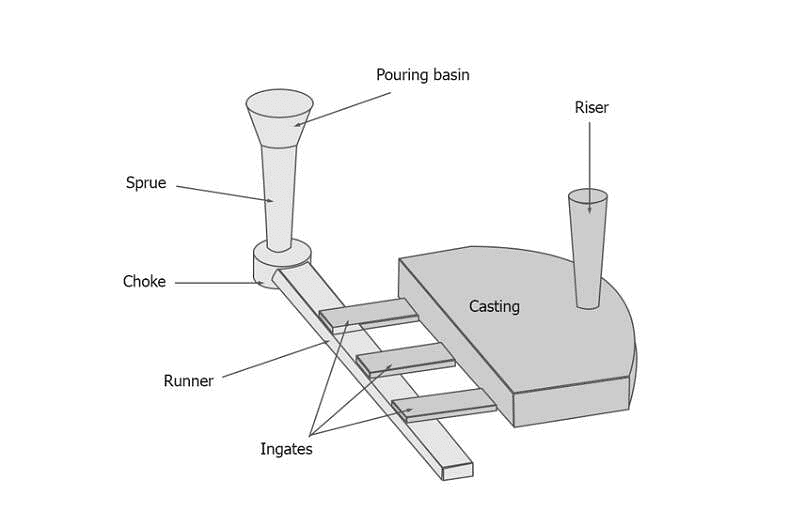
9. Riser
- It is a reservoir of molten metal in the casting so that hot metal can flow back into the mould cavity when there is a reduction in volume of metal due to Shrinkage .
10. Fluid Flow
Continuity: The law of mass continuity states that for the incompressible liquids and in a system with impermeable walls, the rate of flow is constant. Thus,
Q = A1.V1 = A2.V2
Q = Rate of flow m2/s
A = Cross -sectional area of the liquid system
V = Average velocity of the liquid system
According to this law, the flow rate must be maintained anywhere in the system.
- The permeability of the wall of the system is important because otherwise some liquid will permeate through the wall (such as in sand molds) and the flow rate will decrease as the liquid moves through the system.
- Assuming that the pressure at the top of the sprue is equal to the pressure at the bottom and that there is no frictional losses, the relationship between the height and cross-sectional area at any point in the shape is given by the parabolic relationship.

where the subscript 1 denotes the top of the sprue and 2 denotes the bottom moving downward from the top, the cross-sectional area of the sprue must decrease. Depending on the assumptions made, above equation can also be obtained.
Types of Patterns
Patterns are used to mold the sand mixture into the shape of the casting. This may be made of wood, plastic or metal. The selection of a patterns depends on the size and shape of the casting, the dimensional accuracy, the quantity of casting required and the molding process.
(i) Loose Piece Pattern
- These are the single piece pattern incorporating the allowances, generally these patterns are made up of wood. Gating system is cut in the mould manually.
- These patterns are also known as one piece patterns or solid pattern. These are generally used for simple shapes and low quantity production.
(ii) Gated Patterns
- The gating system and runner is the integral part of the pattern. This eliminated the hand cutting of the runner and gates and hence improved productivity.
(iii) Match Plate Pattern
- This produce small size complex object in mass production we can use this type of pattern for producing intricate shape.
- Number or pattern splited along the symmetry and they are added on both sides of a match plate along with gating elements.
- This type of pattern will be used in machine moulding technique.
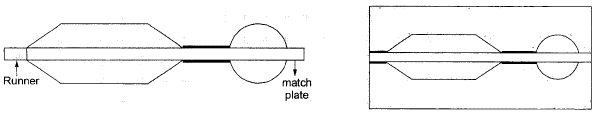 The cope and drag portions of the pattern are mounted on the opposite side of wood or metal plate contouring to the parting line.
 - It is used for production of small size precision casting in mass production. Eg. Piston ring.
(iv) Cope and Drag Pattern
- The cope and drag halves of the mould are made separately.
- It requires accurate alignment by guide and locating pins.
- This types of patterns are used for casting which are heavy and inconvenient for handing and also for continuous production.
- It is used to produce big size casting.
(v) Sweep Pattern
- It is used when 2-D pattern used to produced symmetrical 3-D casting for eg cone, bells of temples.
- To produce 3- dimensional complex cavity using two dimensional plane patterns we can select sweep pattern.
- Two dimension plane patterns will be sweeped inside the mould cavity by 360º by fixing one of its end.
- Due to this cost of producing 3- dimensional pattern will be reduce.
(vi) Follow Board Pattern
- If the pattern is having over hanging portion and lack of strength than due to ramming force, it will get distorted. To support the patterns inside the mould, fallow board is used.
- It is used when thin or overhanging sectionizing casting is required.
(vii) Skeleton Pattern
- This type of pattern will be used to produced large size casting.
- To produce these objects very large size pattern is required.
- To minimize the material consumption on preparing the pattern we can used skeleton pattern


- 3 dimensional skeleton is developed using small wooden work piece to get desired shape and this skeleton is covered with wine mesh.
- It is used to prepare shells and drums.
Properties of Moulding Sand
The traditional method of casting metals is in sand moulds and had been used for millennia. Simply stated, sand casting consists of:(a) Placing a pattern (having the shape of the desired casting) in sand to make an imprint.
(b) Incorporating a gating system.
(c) Filling the resulting cavity with molten metal.
(d) Allowing the metal to cool until it solidifies.
(e) Breaking the sand mould.
(f) Removing the casting.
The production steps for a typical sand-casting operation are shown below:

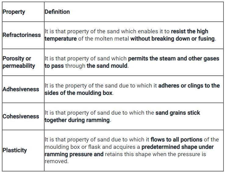
(i) Refractoriness
- It is the ability of moulding sand to withstand the high temperature of molten metals.
- It should be high.
(ii) Green Strength
- The moulding sand that contain moisture 2% to 8% is termed as green sand.
- The green sand should have enough strength so that the mould cavity retain its shape.
(iii) Dry Strength
- When molten metal poured into a mould, the sand around the mould cavity is
quickly converted in dry sand as the moisture in the sand immediately evaporates due to heat in the molten metal. - At this stage it should retain the mould cavity and at the same time withstand the metastatic forces.
(iv) Hot Strength
- It is the strength of the sand that is required to hold the shape of the mould cavity after all the moisture is eliminated and temperature is further increasing.
(v) Permeability
- The gas evolving capability of moulding sand is known as permeability. This will be expressed by permeability number.

V = volume of air passing through the specimen
H = Height of standard specimen
P = Pressure of the air passing through the specimen
A = Area of cross section of cylinder.
T = Time required to pass through specimen

By adding water upto 8%, the permeability value will be increase and beyond 8% if H2O is increased its permeability will start decreasing.
(vi) Grain Fineness Number (GFN)
- GFN will indicate the average grain size distribution in a given moulding sand.
- Greater the grain fineness number more fine the grain size.
- GFN can be determine by conducting sieve shaker test.
(vii) Flowability
- The ability of sand to flow due to ramming force to fire the mould flask area is known as flowability.
(viii) Collapsibility

- Ability of the moulding sand due to which it offers any resistance against the contraction of casting material is called collapsibility.
- During the solid contraction of the casting part if the mould creates resistance cracks will appear over the casting.
- Saw dust or wood powder is added to improve collapsibility.
- Since when molten metal poured wood powder burns to ash due to heat and hence shrinks in size causing the mould near casting to easily collapse and provide resistance less shrinkage.
(ix) Adhesiveness
- The bond formation between two different material between mould sand and pattern.
(x) Cohesiveness
- The bond formation between two similar material i.e between 2 sand grains is known as cohesiveness.
(xi) Toughness
- Ability to resist impact and shock loads by the moulding sands.
- Resistance to stracking, to withstand the force supply by molten liquid metal on the moulds wall is called toughness.
- To get dimensional stability of the casting uniform hardness is require. This can be achieve by uniform ramming.
- Shatter index test is done for toughness testing shocker observed when molten metal is poured.
Note:
Universal Testing Machine: Used for testing green strength
Sand Muller: Used for mixing and preparing moulding sand.
Cup Test: Used for testing formability.
Charpy Test: Used for testing toughness.
Knoop Test: Used for testing microhardness of the material.
Example: 2000 C.C of air is passing through a standard cylinder specimen for 1.5 min. The manometer indicates pressure as 5 gm/cm2, what is the permeability number?
Given, V=2000 c.c; H = 5.08; T = 105 min; P = 5 gm/cm2


Types of Sand
- Green sand
- Dry Sand
- Facing Sand
- Parting Sand
- Baking Sand
(i) Green Sand
- If the sand contains 2.6% of moisture than the sand is called green sand.
(ii) Dry Sand
- The moisture available in the moulding sand evaporates cause of high temperature of molten then the sand is called dry sand.
(iii) Facing Sand
- The sand which is used near the mould cavity with more clay and fine silica sand is called facing sand.
(iv) Parting Sand
- It is a pure silica sand use to avoid Shrinking of the moulding surfaces with other surfaces.
(v) Baking Sand
- Sand which is place at the extreme end of the mould to support the facing sand is known as backing sand. Already used sand can be used as a baking sand.
Additives Used In Moulding Sand
- Wood flour/Saw Dust
It is used in the casting process to improve green strength and collapsibility of moulding sand. - Starch And Dextrin
(i) These are used in the casting process as organic binders.
(ii) It is used to improve resistance to deformation of the mould and improves the skin hardness of the mould. - Iron Oxide And Aluminium Oxide
In order to improves hard strength green iron oxide and aluminium oxide are used in casting process. - Coal Dust, Sea Coal, Silica Flour
(i) These are carbonous material which are used in the moulding sand to improve surface finish and resistance to metal penetration.
(ii) It also increases the fluidity of the moulding sand.
Note:
Composition of moulding sand:
- Silica sand - 70.85%
- Clay - 10.20%
- Water - 3.6%
- Additive - 1.6%
Types of Moulding Method
- Bench moulding
- Floor moulding
- Pit moulding
- Machining Moulding
Bench Moulding
It is used to produce small size moulds only.
Floor Moulding
produce medium size moulds.
Pit Moulding
Machine Moulding
A moulding machine could be defined as a device consisting of several inter-related parts whose function is to transmit and modify various forces and motion so as to aid in the making of a sand mould.
Gating System
The term gate is defined as one of the channels which actually leads in the mould cavity, and the term gating or gating system refers to all channel by means of which molten metal is delivered to the mould cavity.
Functions of A Gating System
The functions of a gating system are :
- To provide continuous, uniform feed of molten metal, with little turbulence as possible to the mould cavity. Excessive turbulence results in the aspiration of air.
- To supply the casting with liquid metal at best location, achieve proper directional solidification and optimum feeding shrinkage cavities.
- To fill the mould cavity with molten metal in the short possible time to avoid temperature gradient.
- To provide with a minimum of excess metal in the gates and risers. Inadequate rate of metal entry, on the other hand, will result many defects in the casting.
- To prevent erosion of the mould walls.
- To prevent slag, sand and other foreign particles from entering the mould.
 Gating System
Elements of Gating System
A gating system is usually made up of:
(1) Pouring Basin
(2) Sprue
(3) Runner
(4) Flow–off Gate
1. Pouring Basin

- This part of the gating system is made on the top of the mould.
- Sometimes, a funnel-shaped opening which serves as pouring basin, is made at the top of the sprue in the cope.
- The main purpose of the pouring basin is to direct the flow of metal from ladle to the sprue, to help maintaining the required rate of liquid metal flow, and to reduce turbulence and vortexing at the sprue entrance.
- The basin should be made substantially large and should be placed near to the edge of the moulding box to fill the mould quickly.
- Also, it must be deep enough to reduce vortex formation and kept full during the entire pouring operation to compensate metal shrinkage or contraction.

- The vertical passage that passes through the cope and connects the pouring basin with the runner or gate is called the sprue.
- The cross-section of a sprue may be square, rectangular, or circular. The sprues are generally tapered downward to avoid aspiration of air and a metal damage.
- Sprues up to 20 mm diameter are round in section whereas larger sprues are often rectangular.
- A round sprue has a minimum surface exposed to cooling and offers the lowest resistance to the flow of metal. In a rectangular sprue, aspiration and turbulence are minimized.
3. Runner
- In large castings, molten metal is usually carried from the sprue base to several gates around the cavity through a passageway called the runner.
- The runner is generally preferred in the drag, but it may sometimes be located in the cope, depending on the shape of the casting. It should be streamlined to avoid aspiration and turbulence.
- A gate is a passage through which molten metal flows from the runner to the mould cavity.
- The location and size of the gates are so arranged that they can feed liquid metal to the casting at a rate consistent with the rate of solidification.
- A gate should not have sharp edges as they may break during passage of the molten metal and consequently sand particles may pass with the liquid metal into the mould cavity.
- However, the gates should be located where they can be easily removed without damaging the casting.
Types of Gates
According to their position in the mould cavity, gating may be broadly classified as:
(b) Parting line Gating
(c) Bottom Gating

Different types of gating systems in casting process are:
Top Gates
- In top gating system, the molten metal from the pouring basin flows down directly into it.
- A strainer, made of dry sand or ceramic material, is mostly used at the pouring basin to control the metal flow and to allow only clean metal to enter.
Parting Line Gates
- In parting line gates, the liquid metal enters the mould cavity from the side of the mould at the same level as the mould joint or parting line.
- The arrangement of providing a gate at the parting line in a direction horizontal to the casting allows the use of devices that can effectively trap any slag, dirt, or sand, which passes with the metal down the sprue.
Bottom Gates
- In bottom gates, the metal from the pouring basin flows down to the bottom of the mould cavity in the drag.
Gating Ratio
- The rate of flow of metal through the mould cavity is a function of the cross-sectional area of the sprue, runners, and gates.
- The dimensional characteristics of a gating system can be expressed in terms of gating ratio.
- The term “gating ratio” is used to describe the relative cross-sectional areas of the components of a gating system taking the sprue base area as unity, followed by the total runner area and finally the total ingate area.
- A gating system having a sprue of 1 cm², a runner of 3 cm², and three gates, each having 1 cm2 cross-sectional area, will have a gating ratio of 1:3 :3.
- The gating ratio reveals whether the total cross-section decreases or increases towards the mould cavity.
Types Of Gating System
Accordingly, there are two types of gating systems in casting process:
(i) Pressurised
(ii) Non-pressurised, or free flowing like a sewer system.
Pressurised Gating System
- Liquid metal will enter into the mould cavity with maximum velocity.
- There is possibility of turbulence, splashing and mould erosion during casting process.

- There is no possibility of air aspiration effect during casting process.
- It is used to produce casting made up of ferrous material example, iron, cobalt.
- Casting yield will be more.
Unpressurised Gating System
- Velocity of liquid metal entering into mould cavity will be high as compare to initial velocity.
- No possibility of turbulence, splashing and mould erosion is present.

- Generally it is used to produce non ferrous material for casting process.
- There is a possibility of air aspiration effect in the runner and sprue base wall.
Objectives of Gating System
- Gating system helps the molten metal to enter the mould cavity without increasing the velocity and turbulence of the molten molten metal within specified time.
- Molten metal has to enter into the mould cavity without eroding gating elements and mould cavity.
- Molten metal has to enter into the mould cavity with full of molten metal through all the gating elements in orders to avoid air aspiration effect.
- We need to design the gating elements such that casting yield is maximum.
- The molten metal has to enter in the mould cavity without any slag particles and impurities.
|
6 videos|104 docs|59 tests
|
FAQs on Metal Casting - 1 - Mechanical Engineering SSC JE (Technical)
| 1. What is metal casting? |  |
| 2. What are the types of patterns used in metal casting? | |
| 3. What is a gating system in metal casting? | |
| 4. What are the types of sand used in metal casting? | |
| 5. What is the purpose of allowance in metal casting? | |


ppt
,Extra Questions
,video lectures
,study material
,Summary
,MCQs
,Viva Questions
,practice quizzes
,Metal Casting - 1 | Mechanical Engineering SSC JE (Technical)
,past year papers
,Metal Casting - 1 | Mechanical Engineering SSC JE (Technical)
,mock tests for examination
,Exam
,Objective type Questions
,shortcuts and tricks
,Free
,Semester Notes
,Important questions
,Sample Paper
,Metal Casting - 1 | Mechanical Engineering SSC JE (Technical)
,Previous Year Questions with Solutions
;


Metal Casting - 1 Free PDF Download
Importance of Metal Casting - 1
Metal Casting - 1 Notes
Metal Casting - 1 Mechanical Engineering Questions
Study Metal Casting - 1 on the App
|
© EduRev
|
Education Revolution
|


|


