Electromagnetic System | Electrical Engineering SSC JE (Technical) - Electrical Engineering (EE) PDF Download
| Table of contents |
|
| What is an Electromagnetic System? |
|
| Magnetic Circuits |
|
| Important Terms Related to Magnetic Circuit |
|
| PYQs: Competitive Exams |
|

What is an Electromagnetic System?
- The electromagnetic system is an essential element of all rotating electric machinery and electromechanical device and static devices like the transformer.
- Electromechanical energy conversion takes place via the medium of a magnetic field or electrical field, but most practical converters use magnetic field as the coupling medium between electrical and mechanical systems.
- In transformers, the electrical energy converts from one electrical circuit to another electrical circuit via the medium of a magnetic field as the coupling medium between one electrical circuit to other electrical circuits.
- The energy storing capacity of a magnetic field is much greater than that of an electric field.
Magnetic Circuits
- The complete closed path followed by the lines of flux is called a magnetic circuit.
- In low-power electrical machines, the magnetic field may be produced by permanent magnets. But in high-power electrical machinery and transformers, a coupling magnetic field is produced by electric current.
Important Terms Related to Magnetic Circuit
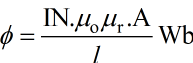
1. Magnetomotive Force (mmf)
- In a magnetic circuit, the magnetic flux is due to the presence of a magnetomotive force (mmf).
- The mmf is created by a current flowing through one of more turns.
mmf = current × number of turns is the coil
mmf = NI (ampere-turns) or (ATs)
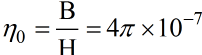
2. Permeability of Free Space
- Suppose a current (I) carrying conductor in free space is shown in figure.
- According to the right-hand grip rule, around the current-carrying conductor, a magnetic flux path is generated.
- Suppose flux density at C, caused by magnetic field intensity H at x is B Tesla and if C is one meter away from x1 then Permeability of free space η0 is given by:
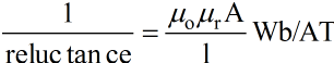
3. Reluctance (Rl)
Opposition offered by the magnetic circuit to magnetic flux is called reluctance.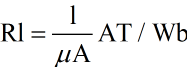
where
l = length of the magnetic path
A = area of cross-section normal to flux path, m2.
μ =μo μr = Permeability of the magnetic material
μ = relative permeability of the magnetic material
μr = permeability of free space = 4π × 10–7 H/m.
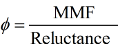
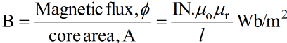
4. Magnetic Flux (ø)
- The magnetic flux may be defined as the magnetomotive force per unit reluctance.
- The direction of magnetic flux produced by the coil can be found by the right-hand grip rule.
5. Right-Hand Grip Rule
It is stated that grip the conductor with the thumb pointing in the direction of conductor current then four fingers give the direction of magnetic flux created by the current.
6. Permeance
- Reciprocal of reluctance is called permeance.
- Permeance =
7. Magnetic Field Density
- It is defined as the magnetic flux per unit cross-sectional area of the core.
8. Magnetic Field Intensity
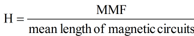
- The magnetomotive force per unit length of magnetic circuit is termed as the magnetic field intensity.
or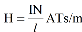
 View Answer
Note:
- In magnetic system there are no magnetic insulators. Even in the best known magnetic insulator air, the flux can be established.
- Energy is needed for establishing the required flux once the requisite flux is created then no more energy is needed in maintaining it.
9. Leakage Flux
- In ideal magnetic circuits, all the flux produced by an exciting coil is confined to the desired magnetic path of negligible reluctance. But in practical magnetic circuits, a small amount of flux does follow a path through the surrounding air.
- Leakage flux is defined as that flux which does not follow the intended path in a magnetic circuit.
- Its effect on the analysis of electrical machinery is carried out by replacing it by an equivalent leakage reactance.
10. Fringing
- As the magnetic flux lines cross the air-gap, the flux bulge out at the end of core. This bulging out of the flux is called fringing.
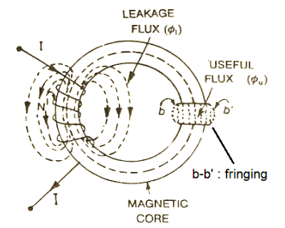
- Longer the air gap, more is the flux fringing.
- The effect of fringing flux is to increase the effective cross-sectional area of the air gap. As a result, flux density in the air gap is not uniform and average flux density gets reduced.
11. B-H Curve
- A B-H curve, also called magnetization curve or saturation curve, is the plot of flux density B as the magnetic field intensity H is varied.
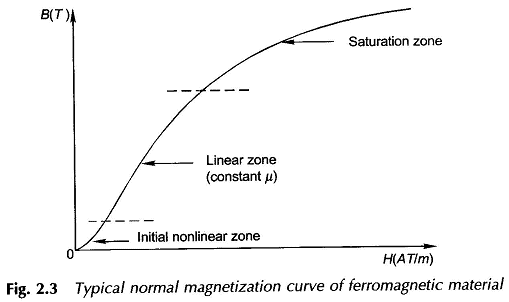
- Figure shows a typical B-H curve of a ferromagnetic material. It has initial non-linear Zone OA, zone from A to C is almost linear and zone beyond C is called Saturation zone.
- The flux density B in the saturation zone increases less rapidly with H as compared to its change in the linear zone.
- As B- H curve is not a straight line, the relative permeability
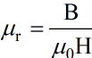 of ferromagnetic material changes with the flux density.
 - In free space or non-magnetic materials, μ0 is constant, therefore B-H relationship is linear.
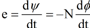
12. Induced Emf
Faraday's law of electromagnetic induction states that an emf is induced in a coil when the magnetic flux linking this coil changes with time.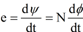
Where
e = emf induced, volts
N = number of turns in the coil
ψ = NØ = flux linkages with the coil, Wb -turns
t = time, seconds
13. Lenz's Law
- When the coil circuit is closed, a current begins to flow in the coil. The direction of this induced emf, of induced current, is governed by Lenz's law.
- According to this law the induced current develops a flux which always opposes the change responsible for inducing this current.
- Lenz's law, in short, is that effect opposes the cause.
PYQs: Competitive Exams
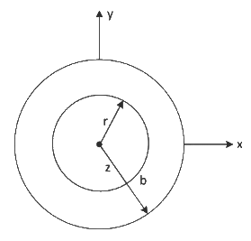
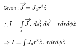
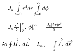
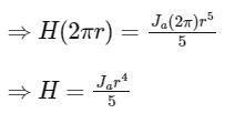
Q1: A long conducting cylinder having a radius b is placed along the z-axis. The current density is  for the region r < b where r is the distance in the radial direction. The magnetic field intensity
  for the region inside the conductor (i.e., for r < b) is [2022]
(a) 
(b) 
(c) 
(d) 
Ans: c
Sol:
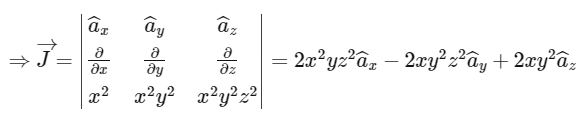
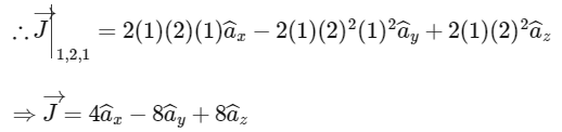
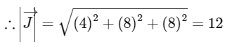
Q2: If the magnetic field intensity  in a conducting region is given by the expression,
 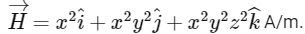 The magnitude of the current density, in A/m2, at x = 1 m, y = 2 m and z = 1 m is [2022]
(a) 8
(b) 12
(c) 16
(d) 20
Ans: b
Sol: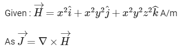
Q3: A solid iron cylinder is placed in a region containing a uniform magnetic field such that the cylinder axis is parallel to the magnetic field direction. The magnetic field lines inside the cylinder will [2017]
(a) bend closer to the cylinder axis
(b) bend farther away from the axis
(c) remain uniform as before
(d) cease to exist inside the cylinder
Ans: a
|
23 videos|94 docs|42 tests
|
FAQs on Electromagnetic System - Electrical Engineering SSC JE (Technical) - Electrical Engineering (EE)
| 1. What is an electromagnetic system? |  |
| 2. What are magnetic circuits? | |
| 3. What are some important terms related to magnetic circuits? | |
| 4. What are some frequently asked questions related to electromagnetic systems in electrical engineering exams? | |
| 5. How can one prepare effectively for questions on electromagnetic systems in competitive exams? | |


Summary
,mock tests for examination
,Semester Notes
,shortcuts and tricks
,Free
,Electromagnetic System | Electrical Engineering SSC JE (Technical) - Electrical Engineering (EE)
,video lectures
,ppt
,Sample Paper
,Exam
,past year papers
,MCQs
,Viva Questions
,practice quizzes
,Electromagnetic System | Electrical Engineering SSC JE (Technical) - Electrical Engineering (EE)
,Previous Year Questions with Solutions
,study material
,Electromagnetic System | Electrical Engineering SSC JE (Technical) - Electrical Engineering (EE)
,Important questions
,Extra Questions
,Objective type Questions
;


Electromagnetic System Free PDF Download
Importance of Electromagnetic System
Electromagnetic System Notes
Electromagnetic System Electrical Engineering (EE) Questions
Study Electromagnetic System on the App
|
© EduRev
|
Education Revolution
|


|


within 7 days!