Chapter 10 - Power System (Part - 2) | Additional Study Material for Mechanical Engineering PDF Download
| Table of contents |

|
| 3. Symmetrical Components & Faults Calculations |

|
| 4. Power System Stability |

|
| 5. Protection & Circuit Breakers |

|
| 6. Generating Stations |

|
3. Symmetrical Components & Faults Calculations
- Fortescue's work proves that an unbalanced system of 'n' related phasors can be resolved into 'n' systems of balanced phasors called the symmetrical components of the original phasors.
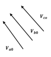
- Three sets of balanced phasors which are the symmetrical components of three unbalanced phasors. Shown in below figures.
Positive Sequence Components Negative Sequence Components
Zero Sequence Components

Where, T = symmetrical transformation matrix and a = 1∠120º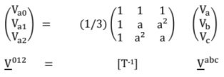
where, T-1 = inverse symmetrical transformation matrix
Average 3 - phase power in Terms of Symmetrical Components:
P = 3 [|Va0 |Ia0| Cosθ0 + |Va1| Ia1 | Cosθ1 + |Va2 |Ia2| Cosθ2]
Sequence N/Ws of a synchronous Generator
Positive sequence Network
The three phase system can be replaced by a single phase network as shown in the below:
The equation of the positive sequence network is Va1 = Ea1 -Ia1. Z1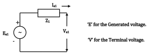
Negative Sequence Network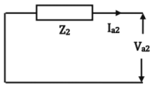
The equation for the negative sequence network is Va2 = - la2.Z2
Zero sequence Network
The equation for the zero sequence network is Va0 = - Ia0Z0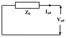
Fault Calculations
Faults can be classified as two types:
- Series faults
- Shunt faults
- Shunt faults are characterized by increase in current and decrease in voltage, frequency and power factor.
- Series faults are characterized by decrease in current and increase in voltage, frequency and power factor.
The series faults are classified as
- One open conductor fault
- Two open conductors fault

The shunt type of fault are classified as:
- Single line to ground fault
- Line to Line fault
- Double line to Ground fault
- Three phase fault
- The first three faults are the unsymmetrical faults.
- The three phase fault is symmetrical faults.
- Severity & occurrence of Faults:
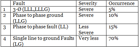
Single Line to Ground Fault
- Most frequently occurring fault.
- Usually assumed the fault on phase - a for analysis purpose, phase - b and phase - are healthy.
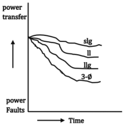
 If = Ia = Ia1 + la2 + Ia0; Ia1 = Ia2 = Ia0 and +ve, -ve and zero sequence networks are connected in series.
single Line of Ground fault with Zf:
Line to Line Fault
If = lb = - Ic = a2Ia1 + ala2 + Ia0 (la2 = - Ia1, Ia0 = 0)


Double Line to Ground Fault: Here sequence networks are connected in parallel.
Va0 = Va1 = Va2 = Va/3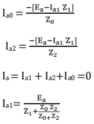
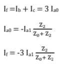
Zero sequence and negative sequence networks are parallel and this is in series to the positive sequence. Double line to ground fault with Zf.
Three Phase Fault
Ia1 = Ea/Z1
Load Flow
Load cannot be same for all time in the system. The power flow idea is to find out the voltage at different bus bar, sub - station, node point & the flow of power on these lines, with given constraints and specifications.
Types of Buses
- Load bus
In this type of bus, Pi and Q1 are known.
The unknowns are |Vi| and δ1. - Slack Bus/ Reference Bus/Swing Bus
This bus is a special type of bus. Here real and reactive powers are not specified only |Vi| and δ1 are known, - Generator/Voltage control/PV Bus
In this type of bus Pi and |Vi| are known. Qi and δ1 are not known.
Power System Network
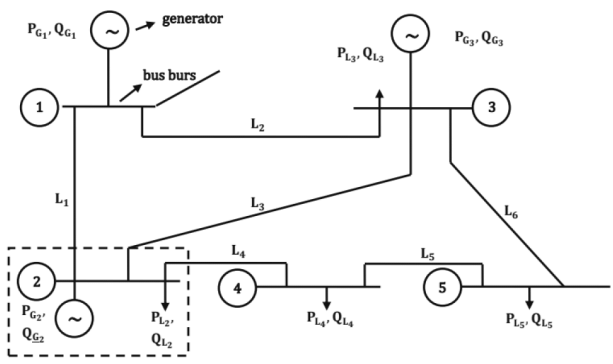
L → Load
G → Load
But Admittance matrix
For a 3-bus system
T11 = Y22 = Y33 ⇒ self admittance. (Driving point admittance)
Y12 = Y21 = Transfer admittance
IBUS = YBUS VBUS
VBUS = ZBUS IBUS ZBUS = [YBUS]-1
VBUS is symmetric matrix
Y12 = Y21 = -Y12
Y13 = Y31 = -Y13
Y23 = Y32 = -Y23
Ybus matrix is sparse matrix. (Sparse means most of the elements of YBUS matrix are zero)
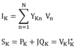
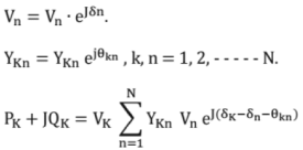
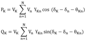
Power Flow Equation
IBUS = YBUS VBUS

Characteristics of Power Flow Equation
Power flow equation is algebraic - static system
Power flow equation is nonlinear - Iterative solution
Relate P, Q in terms of V, δ & YBUS elements, we get P, Q → f (V, δ)
There are two methods to solve these non -linear equations
- Newton Raphson
- Gauss - Seidal method
Newton Raphson (N.R.) method has got quadratic convergence and fast as compared to Gauss - seidel and always converges. But N.R. method requires more time per iteration. Gauss - Seidel has got linear convergence, convergence is affected by choice of slack bus and the presence of sense capacitor.
4. Power System Stability
Stability is the ability to maintain synchronism with the externally connected transmission lines by the synchronous generator in order to deliver the maximum power to either small (or) sudden change in load. The two electrical parameters for the stability consideration are
(i) Supply frequency
(ii) Terminal voltage.
In general the real power is only considered for stability consideration, because any change in load at load end i.e.; real power does reflect in change of rotor position of an alternator.
Steady State Stability: It is the ability to maintain synchronism by delivering maximum amount of real power for a small and gradual variation of load. The rate of change of load is less than rate of change of excitation controller or the frequency of oscillations due to change of load are less than natural frequency of the system. The steady state stability limit can be evaluated by using power-transfer equations by using simulation networks
Case I
Alternator connected to asynchronous load directly. The resistance of alternator is ignored.
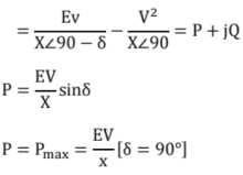

Case II
Alternator supplying power through a transmission line of a certain reactance.
Case III
Vs = E
θ = δ
Because the reactance of generator and transformer are very less when compared to the reactance of transmission line.
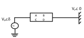

Uncompensated Transmission Line: In short line the total value of x(reactance) is less so the alternator will deliver maximum power without loosing synchronism.
Compensated Transmission Line: In long transmission line the total value of reactance is very high so that alternator may fall out of synchronism, while delivering maximum power. To reduce the net reactance, series capacitor is placed. Such a transmission line is called compensated line.
Methods of improving steady state stability limit;
(i) Operating the system at higher voltages
(ii) Reducing the net reactance of the system. This can be obtained by using parallel lines, double circuit and bundle conductors.
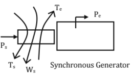
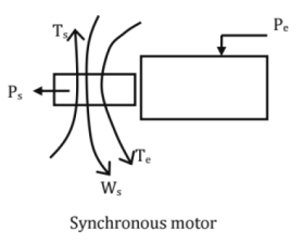
Mechanical and Electrical Power of Synchronous Machine
Swing Equation

Where, M = moment of inertia, and Ps is the mechanical power supplied to the alternator.
Swing equation which is a non-linear differential equation. It describes the relative position of rotor w.r.t stator fixed as a function of time.
Two Machines are Swinging Together
Two alternators are connected to common bus, any change of load will change the rotor position of two alternators is called swinging of two machines.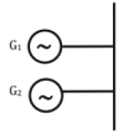
M1 and M2 are angular momentum of two generator. δ1= δ2 = δ and Paeq1 = Pa1 + Pa2
Meq = M1 + M2
Meq = M1 + M2 + ......+ Mn
Two Machines are not Swinging Together
When two alternators are not connected to common bus, only change of load will change the rotor position of one alternator only, then the machines are not swinging together.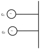
M1 and M2 are angular momentum of two generators.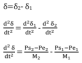
Multiplied both sides by
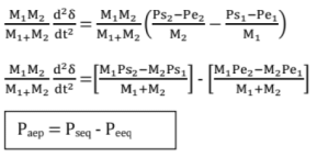

Inertia Constant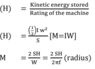

M α H
Swinging of the Machines
Hep = H1 + H2 + ......Hn
Do not Swinging of the Machines
In general swinging of the machines will preferred so that the equivalent inertia will increase which will reduce the swinging of the machines.
Transient Stability
It is the maximum amount of power that can be delivered to the load without loosing synchronism for sudden and large variations of the load due to 3-phase short circuit fault occurred for a time of 5 cycles only. Otherwise, the system will lose synchronism.
Pe1 = Pm1 Sin δo (Maximum power transfer before fault)
X1eq is the transfer reactance before the fault between the source and the load.
= Pm2 Sin δ

= Pm3 Sin δ
Assumptions to Evaluate the Transient Stability
(i) The resistance, the shunt capacitance of generator and transmission lines are ignored. The shunt elements like shunt capacitor (or) shunt inductor at load Bus or generator bus are ignored. The network is represented as transfer reactance.
(ii) The mechanical input is assumed to be constant.
(iii) There is no change in the speed of alternator.
(iv) The damping force provided by damper winding is ignored.
(v) The voltages behind the reactances of the Machines are ignored.
The transient stability can be analyzed by using the swing equation.
The transient state stability can be analyzed by using Equal Area Criterion, or point-by-point method.
Equal Area Criteria: The basis is swing equation.
Multiply both sides the equation 2 d5/dt and integrate w.r.t. time.
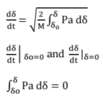
The alternative will experience both acceleration and deceleration when it travels from δ0 to δ due to sudden large disturbance. During acceleration Ps > Pe and during deceleration Ps < Pe.
where there is no change in rotor angle and the speed is synchronous speed.
where the change in rotor angle is zero and the speed is also synchronous speed.
For the system to be stable A1 < A2
For the system to be critically stable A1 = A2
For the system to be unstable A1 > A2
Where A1 = Positive bounded area by Pa (accelerating power) and δ axis.
A2 = Negative area bounded by Pa and δ - curve
Assumptions of Equal Area Criteria
(i) Pa = 0 and W = Ws there is no change in rotor angle.
(ii) Pa = 0 but W ≠ W (or) Pa ≠ 0 but W = WS, there is change in rotor angle.
(iii) The angular momentum should also taken into account to explain equal area criteria.
Factor Affecting Transient Stability
(i) Higher value of 'M'
(ii) Fast acting CB: (SF6) CB
(iii) High speed Governor
(iv) Operating the system at higher operating voltage (or) reducing the net reactance of the system
(v) Using fast acting excitation control and fast acting voltage regulator
(vi) By using dynamic resistor
(vii) By using single pole CB operation
Effect of Grounding on Transient Stability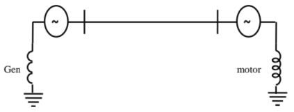
To maintain transient stability the generator will be ground through resistor because it will increase the real power transfer during the fault. So, that the acceleration will reduce.
In case of synchronous motor the reactance grounding is preferred which will not affect the real power supplied to the load of motor. So there will not be any severe deceleration.
5. Protection & Circuit Breakers
Relay: A relay is an automatic device which senses an abnormal condition in an electric circuit and then activates the circuit breaker to isolate the equipment from the fault.
Pick Up Level: The value of the actuating quantity (current or voltage) which is on the threshold (border) above which the relay operates.
Reset Level: The value of current or voltage below which a relay opens its contacts and comes to original position.
Operating Time: The time which elapses between the instant when the actuating quantity exceeds the pickup value to the instant when the relay contacts close.
Reset Time: The time which elapses between the instant when the actuating quantity becomes less than the reset value to the instant when the relay contact returns to its normal position.
Primary Relays: The relays which are connected directly in the circuit to be protected.
Secondary Relays: The relays which are connected in the circuit to be protected through current and potential transformers.
Auxiliary Relays: Relays which operate in response to the opening or closing of its operating circuit to assist another relay in the performance of its function. This relay may be instantaneous or may have a time delay.
Reach: A distance relay operates whenever the impedance seen by the relay is less than a prespecified value. This impedance or the corresponding distance is known as the reach of the relay.
Underreach: The tendency of the relay to restrain at the set value of the impedance or impedance lower than the set value is known as under reach.
Overreach: The tendency of the relay to operate at impedances larger than its setting is known as over-reach.
Functional Characteristics of a Protective Relay
A Protective relay is a device that detects the fault and initiates the circuit breaker to isolate the defective element from the rest of the system.
- Selectivity
- Sensitivity
- Speed
- Reliability
- Simplicity
Types of Relays
- Primary relaying equipment
- Secondary or back-up relaying equipment
Classification of Relays
(1) Principle of Operation
(a) Electromagnetic relays; The Electromagnetic relays used for a.c. and d.c. quantities.
(b) Electromagnetic induction or induction relay: Phis relay used only a.c. quantities.
(c) Electrothermal relays: These are actuated by heat.
(d) Physio - electric relays: Ex: Buchholz relay
(e) Static relay:
(f) Electro dynamic relay: Operate on the same principle as the moving coil instrument
(2) Time of Operation
(a) Instantaneous relays: Operation takes place after a negligibly small interval of time from the application of the current or other quantity causing operation.
(b) Definite time-lag relays: The time of operation is quite independent of the magnitude of current or other quantity causing operation.
(c) Inverse time-lag relays: The time of operation is inversely proportional to the magnitude of current or other quantity which causes operation.
(d) Inverse - definite minimum time lag relays: (1DMT relays). The time of operation is approximately inversely proportional to the smaller values of current or other quantities which causes operation and tend to a definite minimum time as the value increases without limit
(3) Applications
(a) Under current, under voltage, under power relays: which operation takes place, voltage or current or power falls below a specific value
(b) Over current, over voltage, over power relays: which operation takes place when, the voltage, current, and power rises above a specific value.
(c) Directional or reverse current relays: which operation occurs when the applied current assumes a specific phase displacement with reference to applied voltage and the relay is compensated for fall in voltage.
(d) Differential relays: which operation lakes place at some specific phase or magnitude difference between two or more electric quantities.
(e) Distance relays: The operation depends upon the ratio of the voltage and current.
Over Current Relays: In over-current protection, the relay picks up when the magnitude of current exceeds the pick-up level. It includes the protection from overloads, which means machine, or equipment is taking more current than its rated value.
The Over-Current Protection is Provided for the Following Equipment
- It is the basic type of protection used against over-loads and short-circuits in starter windings of motors.
- Transformers are provided with over-current protection against faults in addition to differential relays to take care of through faults.
- The lines can be protected by (i) Instantaneous over-current relays, (ii) Inverse time overcurrent relays, and (iii) Directional over-current relays.
- Utility equipment such as furnaces, industrial installations, commercial and industrial equipments are all provided with over-current protection.
Plug - setting multiplier (P.S.M): It is the ratio of fault current in relay coil to the pick-up current i.e.

For Universal relay torque equation, T = K1I2 + K2V2 + K3VI Cos (θ - τ) + K
For over current relay, K2 = 0, K3 = 0 and spring torque will be '- K'
Therefore T = K1I2- K
K1I2 is the operating torque produced, 'K' is restoring torque produced.
Directional Relay: The over-current protection can be given directional feature by adding directional element in the protection system. Directional over-current protection responds to over-current for-a particular direction flow. If the power flow is in opposite direction, the directional over-current protection remains inoperative.
Directional over - Current Relays
- Directional Relay
- Non-Directional Relay
For Directional Relay K1 = 0, K2 = 0, K = -ve
T = K3VI Cos (θ - τ) + K
Differential Relays: The differential relay is one that operates when the vector difference of two or more similar electrical quantities (either current or voltage) exceeds predetermined value. It should have
- Two or more similar electrical quantities.
- These quantities should have phase displacement {approximately 180°), for the operation of the relay.
- it is used for protection of Alternator (for Internal faults), Transmission lines (Long - using carrier communications, short - using pilot wires)
- This requires two CTs at the two sides of protecting Zone with same current ratio and other characteristics.
- This scheme is also called merz - price circulating current method.
Distance Relay: The operation depends upon the ratio of the voltage and current.
- Impedance Relay
- Reactance Relay
- Mho Relay
(1) Impedance Relay: Torque equation, K2 = -ve, K3 = 0 and 'K' is neglecting (spring torque).
T = K1I2 - K2V2
This means the operating torque is produced by the current coil and restraining torque by the voltage which means that impedance relay is a voltage restrained over current relay.
Operating torque > restraining torque
K1l2 > K2V2
V2 / I2 < K1 / K2
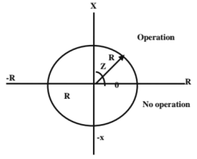
Impedance relay R-x diagram Impedance relay lies within the circle the relay will be operate other wise it will not operate.
Impedance relay normally used are high speed relay, balance beam structure or induction cup structure.
This relay used in Medium Transmission lines
(2) Reactance Relay: Reactance relay is an over current relay with directional restraint Torque equation, K2 = 0, K3 = -ve, K = 0.
T = K1l2 - K3 Vl Cos (θ - τ)
Maximum Torque angle is 90° i.e. τ = 90°.
Therefore T = K1I2 - K3 VI Cos (θ - 90°)b
= K1I2 - K3 VI sin θ
K1l2 > K3 Vl sin θ
(VI / I2) sin θ < K1 / K3
Z sin θ < K1 / K3
X < K1 / K3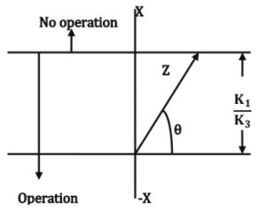
The resistance component of the impedance has no effect on the operation of the relay. It responds only to the reactance component of the impedance this relay used in Short Transmission lines
(3) Mho Relay: Mho relay is a voltage restrained or directional relay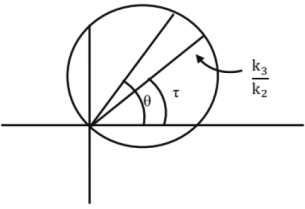
Torque equation, K1 = 0, K2 = -ve, K = O.
T = -K2V2 + K3 VI Cos (θ - τ)
For the relay to operate
K3 VI Cos (θ - τ) > K2V2
V2 / VI < K3 / K2 cos (θ - τ)
Z < K3 / K2 cos (θ - τ)
This relay used in Long Transmission lines
Fuse
The fuse element is generally made up of materials having the following characteristics
(i) low melting point e.g. tin, lead, zinc.
(ii) high conductivity e.g. silver, copper, aluminum
(iii) free from deterioration due to oxidation
(iv) low cost.
Rated Current: The rated carrying current of a fuse element is the maximum current, which it can carry without any undue heating and melting.
Fusing Current: It is the minimum current at which the fuse element melts and opens the circuit to be protected by it. For a round wire the approximate value of fusing current is given by
Where, k is a constant depending upon the metal of the fuse wire d is the diameter of the wire.
Fusing Factor: it is defined as the ratio of minimum fusing current to the current rating of fuse element. Its value will be always more than one.
Prospective Current: The r.m.s. value of the first loop of the fault current is called the prospective current.
Cut off current: The maximum value of the fault current actually reached before the fuse melts is called cut-off current.
Pre Arcing time: This is the time between the commencement of the fault current and the instant that the arc is initiated.
Arcing Time: This is the time between the end of the pre-arcing time and the instant when the arc is extinguished.
Total operating time: It is the sum of pre-arcing and arcing times.
- Fault power is measured in MVA.
Circuit Breaker
The circuit - breakers are automatic switches which can interrupt fault currents. The circuit - breakers used in three-phase systems are called triple -pole circuit breakers. In some applications like single - phase systems single - pole circuit breakers are used.
Arc Phenomenon: The electric arc is a type of flow of electric current between electrodes-or a type of electric discharge between electrodes.
The interruption of D.C. arcs is relatively more difficult than A.C. arcs.
- Arc is a column of ionized gas.
- The arc in the breaker may be initiated either by field emission or thermal emission or ionization
Arc Voltage: It is the voltage that appears across the contacts of the circuit breaker during the arcing period.
High Resistance Interruption is Made in the Following Methods
- by increasing the length of the arc
- by cooling the arc
- by splitting the arc into number of small arcs
- by restrain or confining the arc to a narrow channel.
Low Resistance or Current Zero Method: This method is employed for arc extinction in a.c. circuits only. In this method, arc resistance is kept low until current zero where the arc extinguishes naturally and is prevented from restriking inspite of the rising voltage across the contacts. All modern high power a.c. circuit breakers employ this method for arc extinction.
The Two Main Theories Explaining Current Zero Interruptions
- The recovery rate theory. (Slepian's theory)
- The energy balance theory (Cassie's theory)
Recoveiy Voltage: The power frequency r.m.s. voltage that appears across the breaker contacts after the transient oscillations die out and final extinction of arc resulted in all the poles is called the recovery voltage.
Active Recovery Voltage: It is defined as the instantaneous value of recovery voltage at the instant of the arc extinction.
The Active Recovery Voltage Depends Upon the Factors
- power factor
- armature reaction
- circuit conditions
Expression for Active Recovery Voltage
The active recovery voltage can be represented as
VAR = K1K2K3VmsinΦ
Where K1 is called the demagnetizing factor due to which the recovery voltage will be less than the system voltage,
K2 is a condition factor i.e. it depends on the condition whether the symmetrical fault is grounded or not, i.e. its value is either 1 or 1.5.
And K3 is factor equal to 1 if the active recovery voltage between phase and neutral is to be obtained and its value is √3 if the active recovery voltage between the two lines is required.
Re-Striking Voltage: The resultant transient voltage which appears across the breaker contacts at the instant of arc extinction is known as the re striking voltage.
The expression for restricting voltage for a loss - less line is
Where, v = restriking voltage at any instant t,
V is the value of voltage at the instant of interruption.
L and C are the series inductance and stunt capacitance upto the fault point.
Rate of Rise of Re-Striking Voltage (R.R.R.V)
RR.R.V = Peak restriking voltage KV/p.sec
The Time taken to Rise the Voltage from Zero to Peak Voltage
R.R.R.V = Peak restriking voltage KV/μ.sec t
Time, t = 1/2 fn
Where, fn = frequency of transient oscillators

RRRV is very important parameter for designing circuit breakers.
Resistance Switch
To control the R.R.R.V.
For critical damping
The resistance is connected parallel to the breaker contact or parallel to arc. Some part of current flow through the resistance.
Current Chopping
It is the phenomenon of current interruption before the natural current zero is reached. The current chopping occurs due to rapid deionizing and blast effect and result in very seriously voltage oscillation.
If ia is instantaneous value of arc current where the chop takes place, the prospective value of voltage to which the capacitance will be charged, will be
Where, L is series inductances and C is stunt capacitance
Classification Of Circuit Breakers
(a) Oil circuit breakers which employ some insulating oil for arc extinction.
(b) Air-blast circuit breakers in which high pressure air-blast is used for extinguishing the arc.
(c) Sulphur Hexa fluoride circuit breakers in which Sulphur Hexa Fluoride (SF6) gas is used for arc extinction as well as insulator.
6. Generating Stations
Steam Power Plants (Synopsis)
Steam power plant: A generating station which converts heat energy of coal combustion into electrical energy is known as a steam power station.
Schematic Arrangement of Steam Power Stations
The main and auxiliary equipment in a thermal power plant are.
- Coal and ash handling plant
- Steam generator or Boiler
- Steam Turbine
- Condenser
- Cooling towers
- Feed water heater
- Super heater
- Economiser
- Airpreheater
- A. C. Generator (or) Alternator
- Exciter
Advantages of Steam Power Plants
- Power stations can be located near the load centers.
- It requires less space as compared to the hydro - electric power station.
- Requires less transmission and distribution.
- Long summer will not affect the power generation like hydel power.
- Long gestation period.
Disadvantages of Steam Power Plants
- It pollutes the atmosphere due to the production of large amount of smoke and fumes
- It is costlier in running cost as compared to hydro-electric plant.
Efficiency of Steam Power Station
The overall efficiency of a steam power is quite low (about 29%) due to mainly two reasons.
(a) Huge amount of heat is lost in the condenser.
(b) Heat losses occur at various stages of the plant.
Thermal efficiency: The ratio of heat equivalent of mechanical energy transmitted to the turbine shaft to the heat of combustion of coal is known as thermal efficiency of steam power station.
Overall efficiency: The ratio of heat equivalent of electrical output to the heat of combustion of coal is known as overall efficiency of steam power station.
Overall efficiency = thermal efficiency x electrical efficiency
Hydroelectric Power Station
A generating station which utilizes the potential energy of water at a high level for the generation of electrical energy is known as a Hydroelectric power station.
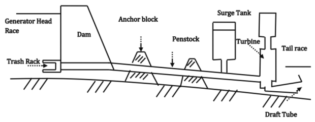
Schematic Arrangement of Hydroelectric Power Station
The Hydroelectric Power Station mainly consists of the following:
- Hydraulic Structure
- Water turbine
- Alternator
Classification based on plant capacity
- Micro-hydel plants: - Capacity less than < 100 kw
- Mini-hydel plants: Capacity between 101-1000 kw
- Small-hydel plants: Capacity between 1001 - 5000 kw
- Medium hydel plants: - Capacity between 5 - 100 MW
- High hydel plants: - Capacity between 101 - 1000 MW
- Super hydro plants: - Capacity more than 1000 MW
Calculation of Hydro Electric Potential
Water head: The difference of water level is called the water head.
Gross head: The total head difference between the water levels in head race (upstream side) and tailrace (downstream side) is called as gross head or total head.
Net head or effective head: Gross head - Head loss in the Conveyor system from Head race to the entrance of turbine due to friction
It is equal to the difference of total head at the point of entry and at the point of exit of the turbine.
Rated head: Head utilized in doing work on the turbine is called the rated head.
Rated head = Net head - Loss in guide passage and entrance of the turbine
Water Power equation (or) output equation
Output Power, P = w.Q. H. η kw
Where, w = specific weight of water = 9.81 KN/m3,
H = net head of water in meter on the turbine
Q = quantity of water in m3 /sec
η = over all efficiency of the system.
where, w = specific weight of water =1000 kg/m3
Advantages of Hydroelectric Power Stations
- No cost of fuel
- Low maintenance cost
- High plant efficiency
- Plant is free from pollution
- Used as multi-purpose projects (irrigation, flood control etc)
- Cost per unit is less.
- Suitable for variable heads and to act as a peak load plant.
Disadvantages of Hydroelectric Power Station
- The area required is more
- High initial cost
- Located in remote area and require more cost on Transmission lines.
Nuclear Power Plants
Nuclear Power Plants: A generating station in which nuclear energy is converted into electrical energy is known as a nuclear power station.
Schematic Arrangement of Nuclear Power Station
The Nuclear Power Station mainly consists of the following:
- Nuclear Reactor
- Heat Exchanger
- Steam Turbine
- Condenser
- Alternator
Advantages of Nuclear Power Plants
- The amount of fuel required is quite small. Therefore, there is a considerable saving in the cost of fuel transportation.
- A nuclear power plant requires less space as compared to any other type of the same size.
- It has low running charges as a small amount of fuel is used for producing bulk electrical energy.
- Running costs are less.
- Reliable and economical for bulk generation.
Disadvantages of Nuclear Power Plants
- Nuclear power plants are not suitable for varying loads, as reactors cannot be easily controlled.
- It is difficult to make the casing of the reactor, such as high temperature, neutron bombardment.
- The disposal of the products which are radioactive is a major problems.

|
1 videos|30 docs|57 tests
|
|
1 videos|30 docs|57 tests
|

|
Explore Courses for Mechanical Engineering exam
|

|
 If = Ia = Ia1 + la2 + Ia0; Ia1 = Ia2 = Ia0 and +ve, -ve and zero sequence networks are connected in series.


