Chapter 11 - Machines (Part-1) | Additional Study Material for Mechanical Engineering PDF Download
1. Transformer
Single Phase Transformer
- Transformer is a static device and has no moving parts.
- Electrically isolated, magnetically coupled.
- Transformer has 2 or more windings.
- A transformer is not an energy conversion device and there is no change in frequency.
- Voltage and current change simultaneously.
- Two types of losses occur viz. Core and Copper losses during operation.
- Transformers require very little care and maintenance because of their simple, rugged and durable.
- The efficiency of a transformer is high because there are no rotating parts, it is a static device.
- The efficiency of a 5 KVA transformer is of the order of 94-96%.
- The efficiency of a 100 MVA transformer is of the order of 97-99%.
- Transformer is responsible for the extensive use of a.c. over d.c.
Constructional Details
- Core: Silicon steel or sheet steel with typically 4% silicon is used.
- The sheets are laminated and coated with an oxide to reduce iron losses including eddy current losses.
- The thickness of lamination is about 0.35 mm for 60 Hz operation and about 5 mm for 25 Hz operation.
- The core provides a path of low reluctance with permeability of the order of 1000.
Windings
- Conventional transformer has two windings.
- The winding which receives electrical energy is called primary winding.
- The winding which delivers electrical energy is called secondary winding.
- Windings are made of High grade copper if the current is low.
- Stranded conductors are used for windings carrying higher currents to reduce eddy current loss.
Methods of Cooling
- Natural Radiation .... low voltage and output ratings. (500V, 5 KVA).
- Oil filled and self cooled ..... large sized transformers. (132 KV, 100 MVA).
- Forced cooling with air blast ..... Transformers with ratings higher than 33 KV and 100 MVA.
Conservator Tank: Due to variations in load and climatic conditions, the oil in oil-filled, self- cooled transformers expands or contracts and high pressures are developed which may burst the tank and hence a conservator tank needs to be used.
Bushings: To provide proper insulation to the output leads to be taken from the transformer tank.
Breather: To prevent moisture and dust from entering the-conservator tank oil, breather is provided.
Types of Transformer
- Core type: Copper windings surround core (Ex. distribution transformers).
- Shell type: Iron core surrounds the copper windings.
Core-Type Transformers: Two types
(i) Core-type
(ii) Distributed core type.
- In a simple core-type transformer, there is a single magnetic circuit,
- The vertical members of the core are called limbs, and the horizontal members are called yokes
- Each limb of a core-type transformer carries a half of primary windings and a half of secondary windings.
- In a distributed-core type transformer, the windings are on the central limb.
Shell-Type Transformers
- A shell type transformer has two magnetic circuits parallel to each other.
Humming noise is due to MAGNETOSTRICTION in the core due to varying flux, and to reduce this noise, transformers are provided with good bracing.
Principle of Operation
- Transformer works on the principle of mutual induction.
- The voltage per turn of the primary and secondary windings is the same since the same mutual flux cuts both the windings, if both the windings are identical in cross-section.
- The ratio of the induced emf's = Ratio of the turns.
- Since E1 ≅ V1 and E2 ≅ V2 ∴ V1/V2 = T1/T2
- In a loaded transformer, the primary draws a current so that mutual flux is maintained constant.
- Since no-load primary AT are very small compared to full-load AT, I1T1 = I2T2.
- I1/I2 = T2/T1 = V2/V1 i.e, V1L1 = V2L2. Primary VA = Secondary VA.
E.m.f Equation:
Voltage applied to the primary and the magnetic flux set up in the core are assumed to be sinusoidal.
Similarly E2 = 4.44 fT2φm
E1 and E2 are in phase and lag behind φm by an angle of 90°
Losses and Efficiency
- Since a transformer is a static device, there are no mechanical losses.
- There will be only magnetic (hysteresis and eddy current losses) and copper losses due to the flow of current through the windings.
- Hysteresis loss is proportional to the maximum value of flux density raised to the power of 1.6 and the supply frequency Le., Bm1.6f.
- The eddy current losses are proportional to the square of the maximum flux density and the square of the frequency and the square of thickness of laminations. i.e., Bm2f2.t2.
- The flow of current through the windings gives rise to the copper losses, viz., I12 r1 and I22 r2.
- The magnetic losses are present as long as the primary is energized.
- Since the no - load current is only of the order of 5% of the rated or full load current, the no load copper loss in the primary winding is neglected. So, the no load input to a transformer is taken as the magnetic loss or the iron or the core loss. It is assumed to be same under all operating conditions, right from no load to full load (or even slight over load). It is denoted as Pi.
- The copper losses vary with the value of the secondary (and hence the Primary) current. The copper loss corresponding to the rated value of the current is called the Full load copper loss. We shall designate it as Pc.
- The efficiency (sometimes called the commercial efficiency) of a transformer is the ratio of the power output and power input, both expressed in the same units (Watts, Kilowatts or Megawatts).
- Let be the KVA of the transformer, x be the fraction of the full load at which the transformer is working (0 ≤ x ≤ 1.0 usually), and cos φ be the power factor of the load. Then the efficiency is given by

- At maximum efficiency operation, the total losses = 2 Pi = 2x2 Pc, since x = √ (Pi/ Pc)
Equivalent Circuit: By making use of the equivalent circuit, the performance indices such as efficiency, voltage regulation etc., can be determined.
The Exact Equivalent Circuit of a Transformer: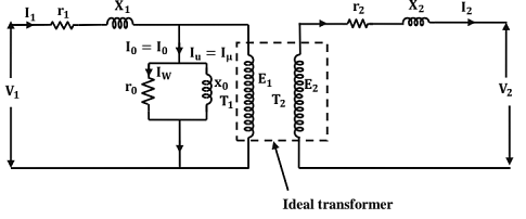
Approximate Equivalent Circuit:
- In the approximate equivalent circuit, the voltage drop due to the flow of I0 through r1 and x1 is neglected. This is justified since 10 is very small compared to the rated full load current.
- The approximate equivalent circuit can further be simplified as (r1 & r21) are in series and (x1 & x21) are in series, as shown in the figure below.

- Here, R1 = (r1 + r21), is called the equivalent resistance of the transformer referred to the primary side.
Similarly, X1 = (x1 + x21), is called the equivalent reactance of the transformer referred to the primary side.
Note
- In referring the equivalent circuit from one side to the other side, the resistance, reactance and impedance get multiplied by the SQUARE of the turns ratio; the voltage by the turns ratio.
- The h.v winding will have higher impedance and the 1.v winding the lower impedance.
- Current gets multiplied by inverse of turns ratio while referring from one side to the other side.
Copper Losses In the Transformer
Phasor Diagram
The phasor diagram of a single phase transformer may be drawn as follows:
Consider secondary voltage V2 as the reference phasor, i.e., V2 = V2∠0. Let the p.f. of the load be cos∅2. (lagging) Then, secondary current, I2 = I2∠∅2.
Now, the secondary e.m.f E2 = V2+I2 ∠-∅2 (r2+j x2) Now, let us assume that the transformer is a step - down transformer, so that the transformer is a step - down transformer, so that E1>E2. Also, since E1 and E2 are in phase, E2 is extended to give E1 = E2 (T1/T2). Now, Iμ leads E1 and E2 by 90°. Now, Iμ is drawn in phase with ∅m and lw leading ∅m by 90°.
I0 = Iμ + Iw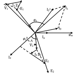
The secondary current referred to the primary side, I21 = I2 (T2/T1). Now; l1 = (-I21) + lo and V1 =(-E1) + I1 (r1 + jx1). The angle between V1 and I1 is the p.f. angle of the primary side, i.e., the primary p.f. = cos∅1.
Voltage Regulation of a Transformer
The per - unit voltage regulation (No - load secondary voltage - Rated secondary voltage)/ Rated secondary voltage
[% regulation = (p.u. regulation) x 100]
From the approximate equivalent circuit and the corresponding phasor diagram, an expression for the p.u. voltage regulation can be obtained. 
Where, ε = p.u voltage regulation, εr p.u. resistance = (l1R1)/V1 = (I2R2)/V2
εr = p.u. reactance = (I1x1)/V1 = (i2X2)/V2
+ for lagging p.u. and - for leading p.f. [I1, V1 etc. are the rated values].
Condition for Maximum Voltage Regulation
φ = tan-1 [X1/R1] = tan-1 [X2/ R2]. Maximum regulation occurs at a lagging p.f.
Condition for Zero Voltage Regulation
φ = tan-1 [R1/ X1] = tan-1 [R2/X2], Zero voltage regulation occurs at a leading p.f.
The exact voltage regulation is given by 
Testing of Transformers: The usual tests conducted on a transformer are:
(i) Open circuit test
(ii) Short circuit test and
(iii) Sumpner's Test (or) Back-to-Back test.
OC Test
- The open circuit test is conducted to determine the core losses and the parameters of the magnetizing admittance of the equivalent circuit
- It is preferable to apply the rated voltage to the Lv. winding, keeping the h.v. winding open.
- If 'P0' is the no-load power input, 'Vo' (rated voltage), 'Io' and 'cosφ' are the no-load current and p.f., we have Po = Vo lo cos φ0.
SC Test
- For conducting the short circuit test one of the windings is to be short circuited and a reduced voltage of such a magnitude as to cause the rated current (preferably) to flow through the windings.
- Since the h.v. rated current is less, the h.v. winding is energized and the Lv. winding is short circuited.
- Let 'Isc' be the current, 'Vsc' be the voltage and 'PSC' be the power input, respectively, on short- circuit. Then

Sumpner's Test
- To overcome the drawbacks of the o.c. and s.c. tests, Sumpner's test is conducted. It is a back- to-back test.
- Two identical transformers are required. The primaries are connected in parallel across the supply voltage and rated voltage of the winding is impressed.
- The secondaries are connected in series opposition, so that the resultant voltage acting around the closed circuit formed by the secondaries is zero.
- To circulate the current through the secondaries (and hence in the primaries), a voltage is injected into the circuit. By suitably adjusting the value of the injected voltage, both the secondaries can be made to carry the rated (or any desired value) of the current.
- The wattmeter connected on the primary side gives twice the iron loss of each transformer. Similarly, the ammeter reads twice the no load current of each transformer.
- The wattmeter connected in the secondary circuit reads twice the copper loss corresponding to the short circuit current, ISC and VSC equals twice the impedance drop of each transformer.
All-Day Efficiency of a Transformer
- A distribution transformer is always energized on the primary and the secondary supplies varying loads.
- Since the secondary supplies varying loads (depending upon the requirements of load by the consumers), the copper losses vary from time to time.
- The all day efficiency is normally less than the commercial efficiency.
- For calculating the all day efficiency, we should know the daily load cycle.
- Steps for calculating the all day efficiency:
(i) Calculate the output energy in Kwh or Mwh.
(ii) Calculate the loss of energy due the iron losses as 24 x Pi Kwh or Mwh
(iii) Calculate the copper losses as x2Pct Kwh or Mwh for the various time intervals.
(iv) Calculate the input as the sum of the above three, and hence calculate the all day efficiency.
Parallel Operation of Transformers
- As the load requirement increases, more and more number of transformers are to be connected in parallel since the terminal voltage is to be the same.
- The conditions to be satisfied for the successful parallel operation of transformers may be classified as NECESSARY conditions and PREFERABLE conditions.
- Necessary Conditions
(i) In the case of Single phase transformers, the polarities must be same.
(ii) In the case of 3-phase transformers, in addition to condition (a), the phase sequence must be the same and there must be 0° phase displacement.
(iii) The turns ratio also must be approximately equal. - The Preferable Conditions
(i) The no-load secondary e.m.f's must be the same.
(ii) The per-unit impedances must be equal in order that the transformers share the load proportional to their capacities.
(iii) The ohmic values of the impedances must be in the inverse proportion to the capacities.
(iv) The 'X/R' ratios of the transformers must be the same in order that the p.f.'s be equal.
If 'EA' and 'EB' are the no-load induced e.m.f's of two transformers, 'IA' and ;IB‘ are the currents delivered and 'ZA' and 'ZB' are the Ohmic impedances referred to the L.V. sides of the two transformers, and 'ZL' is the load impedance, then
Let 'S', 'SA' and 'SB' be the total complex power, the complex power delivered by the transformer 'A' and that delivered by the transformer B', respectively.
Then, SA =S[ZB/(ZA+ ZB)] (Ohmic values are to be used)
SB = S [ZA/( ZA + ZB)]
Three Phase Transformation
- Three phase transformation can be obtained by having a single 3-phase transformer. But, if a fault were to be developed, all the loads connected to the transformer will be interrupted.
- Three phase transformation can also be obtained by connecting 3 Nos. single phase transformers in various configurations to form a 3-phase Bank. A modification of delta/delta connection known as Open-delta or Vee connection makes it possible to supple three phase loads, even if one of the transformers develops a fault.
Four basic configurations are possible: (Primary/Secondary): Star/Star, Star/Delta, Delta/Star and Delta/Delta.
Transformer Polarity
Standard markings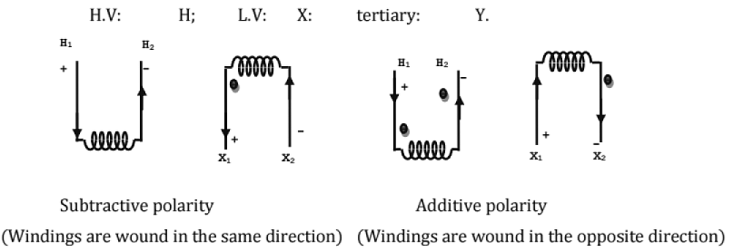
Polarity Test
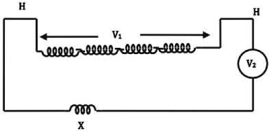
- A.C. Polarity Test:
A.C. voltage is impressed on the h.v. winding, say 'V1'.
If V2>V1, polarity is additive.
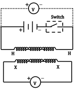
If V2<V1, polarity is subtractive. - D.C. Polarity Test
The cell in series with the switch is placed across any of the windings. The voltmeter is so connected as to get an Up-scale deflection. The voltmeter is now transferred to the other side.
The switch is suddenly opened and the deflection of the voltmeter is observed, if the deflection is up-scale, the polarity is additive; If the deflection is downscale, the polarity is subtractive.
Three-Phase Transformation
(i) Delta-Delta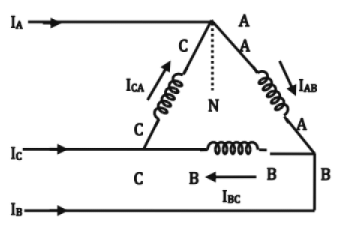
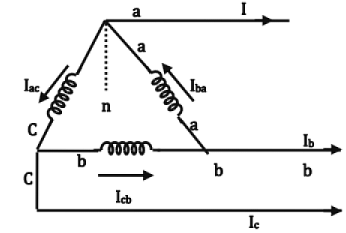
Please note that the directions of the currents 
The symbol is Ddo. Where, D →H. V. side Δ; d→L.V. side Δ; 0→zero phase difference
By reversing the connections of the phase windings on either side, the phase difference becomes 180°. So, the connection is Dd6.
If three individual transformers are used, even if one transformer fails, the other two can be operated in open - delta.
(i) Star-star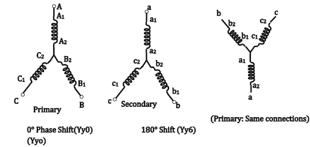
(ii) Delta-Star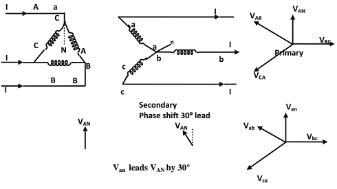
(iii) Star - Delta: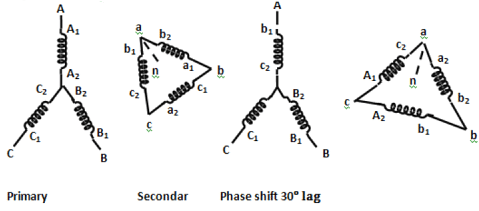
(iv) Delta -Zigzag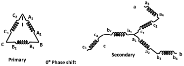
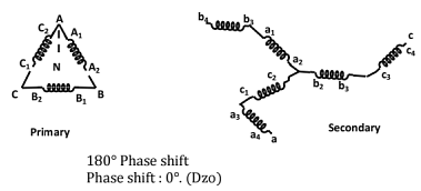
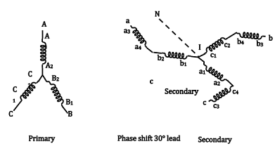
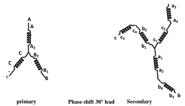
(vii) Open - delta (v-v or v- connection):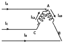
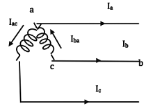
Transformer of the B- Phase is removed (on both the primary and secondary sides).
- the currents in the secondary windings are
Iba= Ia, Iac = Ic On the primary side, IB = -IAB; IC = ICA - One of the windings (transformers) operates at a p.f. of cos(30 + θ) and the other at cos(30 - θ).
- If no transformer is to be overloaded, only 0.866 of the combined capacity is available in open delta connection. (This is also equal to 0.577 of the total 3- phase capacity)
- The factor 0.866 is called the utility factor or utilization factor. [Let the capacity of each single phase transformer be 100KVA.]
(viii) T- connection
It is used for 3-phase to 3- phase transformation using two transformers only.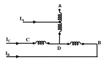
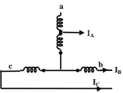
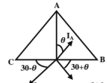
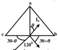
(a) If the two transformers are of identical voltage ratings, there must be a tapping at 50% of the main transformer 86.6% of the teaser transformer.
Three-phase to 2-phase transformation (or vice-versa):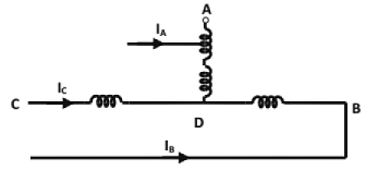
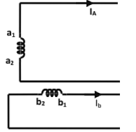
(a) Scott-connection is used
- to supply two-phase furnaces
- to interconnect 2-phase systems with 3-phase systems.
- to supply 3-phase system may be 3-wire or 4-wire.
Auto-Transformers
- An autotransformer uses a single winding only. A part of the winding is common to both the primary and the secondary sides.
- The input and output sides are electrically connected (unlike in a 2-winding transformer).
- There is a superimposition of the input and output currents in the part of the winding common to primary and secondary.
- Power is transferred from the primary to the secondary both inductively and conductively.
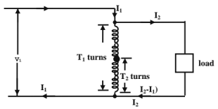
Power transferred inductively
=V2I2(1-K)
Where K=V2/V1=transformation ratio.
∴ Power transferred conductively=(K) (output).
Saving in conductor material:
Conductor material =(in auto-transformer) / (2-winding transformer) = 1-K
Disadvantage: Since the h.v. and l.v. windings are electrically connected, a fault on the h.v. side may subject the l.v. side of the transformer to a high value (= h.v. voltage).
Advantages: (i) leakage reactance is reduced, (ii) Higher efficiency.
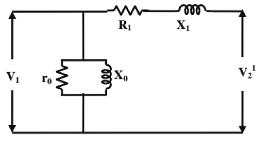
Equivalent circuit: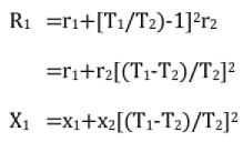
(KVA rating as auto-transformer / KVA rating as 2-winding transformer)
=1/(1-K), where K=V2/V1
(Full-load losses of an auto-transformer / Full-load losses of a 2-winding transformer) =(1-K)
(p.u. impedance drop as an auto-transformer / p.u. impedance drop as 2-winding transformer) =(1-K)
Tertiaiy Windings: A transformer may have a third winding in addition to the normal primary and secondary windings. It is called a tertiary winding.
Tertiary windings are normally delta-connected to provide a path for zero- sequence currents in the case of single line or double line to ground faults. The unbalanced produced by these unbalance ground faults is reduced.
Equivalent Circuit:
The parameters can be determined by conducting short-circuit tests, using any two windings and leaving the third winding open.
Let r12 and x12 be the p.u. resistance and reactance determined using primary and secondary windings (keeping the tertiary open).
Regulation: The regulation of the individual windings can be written approximately as
∈2= k1(rcosφ1 + x1sinφ1) KVA loading kl at a p.f. of cosφ1.
Similarly,
2. Induction Motors
Induction Motors
- Cheap, robust, efficient and reliable.
- Good speed regulation, less maintenance. Reasonable overload capacity.
- Two parts
1. Stator 2. Rotor
Stator
- High grade alloy steel laminations - to reduce eddy current losses. Laminations are slotted on the INNER periphery and are insulated from one another.
- Laminations are supported in a stator frame: Cast iron or fabricated steel plate.
- Winding may be Y-or-A-connected.
Rotor
- Thin laminations of the same material as stator.
- Laminations are slotted or, the outer periphery.
Two types of Rotors:
(i) squirrel Cage Rotor (or) Supply Cage Rotor.
(ii) Phase Wound (or) Wound Rotor. These are also called "Slip Ring 'I.M's".
Cage Rotor
- Cylindrical laminated core with slots NEARLY parallel to the shaft axis and are SKEWED.
- Each slot contains an UNINSULATED bar conductor of aluminum or copper.
- Short-circuited at the ends by heavy end rings of the same material.
Skewing of cage rotor offers the following advantages.
- More uniform torque is produced.
- LOCKING tendency of the rotor is reduced or crawling phenomenon become less prominent.
Slip -Ring Rotor:
- Slotted armature.
- Insulated conductors are housed in the slots.
- Three-phase double layer distributed winding.
- The rotor winding are connected in star.
- The open ends are connected to slip rings.
- Brushes resting on the slip rings are connected to three variable resistors connected in star.
- External resistors:
(i) to increase the starting torque and decrease the starting current.
(ii) to control the speed of the motor. - A cage motor has a higher efficiency and higher p.f. than a slip-ring I.M.
- A wound rotor machine has a high starting torque and a low starting current.
- When 3 -phase winding displaced in space by 120° are supplied by 3- phase currents displaced in time by 120°, a magnetic flux that rotates in space at synchronous speed
 is produced.
 - The resultant flux is Independent of time and is equal to (3/2 times the maximum flux per phase).
- The resultant flux rotates in space with an angular velocity 'ω',
ω = 2π f elect rad/sec and
and 
where Ns = synchronous speed
P = No. of pole pairs
(i) The direction of rotation of flux depends upon the phase sequence.
(ii) A 3- phase i.m. Is self - starting.
(iii) An induction motor cannot run at synchronous speed.
(iv) 'ns - n' is called slip speed.
(v) The slip speed expresses the speed of the rotor relative to the field.
(vi) Rotor frequency depends on slip and is equal to slip times the supply frequency.
Rotor Current
(a) Stand still conditions
(b) At a slip 's'
Rotor Cu loss = s(Rotor power input) = sPg
- The term ‘sPg' is called " SLIP POWER”
- Mechanical power developed = (1-s) pg.
Pg = Power transmitted from stator to rotor via air gap and called power across air gap.
∴pg: Pm : Rotor Cu losses = 1: (1-s ) :s  Where Td is the developed torque.
- Torque available at shaft = (Developed torque) - (Friction and windage torque).
Torque of an Induction Motor: Electrical power generated in rotor

where k =  = a constant ( where ns = rps (round per second))
Starting Torque: At start, s = 1. Therefore, starting torque may be obtained by putting s = 1 in the expression for torque.
The starting torque is also known as standstill torque.
That is, the starting torque is proportional to the square of the stator applied voltage.
Torque at Synchronous Speed: At synchronous speed, s = 0, and therefore τd = 0. That is, at synchronous speed, developed torque is zero.
Condition for Maximum Torque: The value of torque developed is maximum when,
R2 = X2s. This gives 
This relation shows that the maximum torque is independent of rotor resistance.
If sM = value of slip corresponding to maximum torque, then, The speed of the rotor at maximum torque is NM = Ns (1 - sM)
From the equation for maximum torque the following conclusions can be drawn:
- Maximum torque is independent of rotor circuit resistance.
- Maximum torque varies inversely as standstill reactance of the rotor.
- The slip at which the maximum torque depends upon the rotor resistance (sM = R2/X20).
Maximum Torque at Starting: The starting torque will be a maximum when
or R2 = X20
Torque - Slip And Torque - Speed Characteristics: Greater the value of R2, greater is the value of slip at which maximum torque occurs. It is also seen that as the rotor resistance is increased, the pull - out speed of the motor decreases, but the maximum torque remains constant.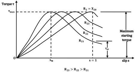
Starting torque α (square of the stator applied voltage)
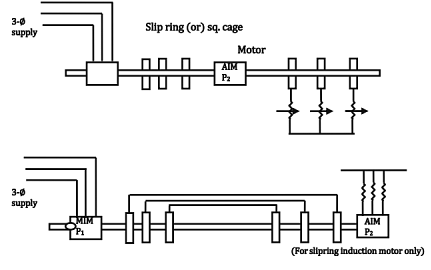
Cascade Connection:
- Slip power of main I.M is fed to Auxiliary I.M. The l.M's are mechanically coupled.
- M.l.M. should be a slip ring l.M. It is connected to supply.
- The A.l.M may be a slip ring or a squirrel cage motor.
The stator of A.1.M can be connected to the rotor of M.l.M (or) The rotor of A.I.M. can be connected to the rotor of M.l.M.
Let P1 and P2 be the no. of poles , f1 and f2 be the frequencies of input voltages and s1 and s2 be the per unit slips of MJ..M and A.l.M. respectively. Then,
Synchronous speed of M IM =Ns1 = (120 f1 /p1) ...... (1)
Synchronous speed of A IM = Ns2 = (120 f2 /p2) ....... (2)
Rotor speed of M IM = N = [(120f1/p1) (1- s1)] ......... (3)
Rotor speed of A IM = N = [(120f2/p2) (1 - s2)] .......... (4)
(A I M is connected mechanically to MIM)
When the torques of the two motors are in the same direction.
(or) N = (120f2/p2) [1 - (2 - s2)]
= (120f2/P2) [(s2 - 1)] ............ (5)
If the torques of the two motors are in opposite directions.
Now, input frequency of AIM, f2 = sf1 ....... (6)
Torques in the same direction:
Now the slip 's2' of A I M operating with s/c secondary will be very small.
∴ p1s2 can be neglected
∴ s2 = p2/(p1 + p2)
∴ N - Ns1 (1 - s1) - (120f1/p1) [1-p1)] / [P1+p2]
= (120f1/p1) [(p1+p2-p2) / ( p1+ p2)]
= (120f1)/(p1+P2)........(8)
If the MIM operated alone, NSM = (120f1 /p1) Torques in opposite directions
N = (1-S1) / P1 = [(120(s1 f1) /p2] [-1 + S2]
i.e., 
Neglecting p2s2; s1=p2/(p2-p1)
∴ N = (1-s1) Ns1 = 1 - [p2/ (P2-P1)] (120 f1/p1) = 120f1/(P1+p2).
If the A I M is operated alone NSA = (120 f1 /p2)
Thus, four different speeds are possible by cascade connection of 2 l.M's.
- Since the net torque is greatly reduced, differential cascade connection is rarely used.
- In the cumulative cascade connection, when the set is stated, supply voltage at frequency 'f1'.
Ratio of Mechanical power outputs: The mechanical power outputs of the motors are approximately in the ratio (1-s1) :s1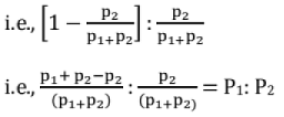
Starting of Induction Motors:
- An IM at rest is like a transformer with a short- circuited secondary.
- If started at full-voltage, the starting current is of the order of 5 to 8 times the full -load current.
- The wound -rotor lM's are started by introducing external resistance across the slip-rings.
- The wound-rotor IM is especially suitable for staring loads having large initial friction.
- Squirrel cage motors are started by applying a reduced voltage at starting and then increasing to the full line voltage as the motor picks up the speed.
Direct starting (or DOL, Direct On - line Starting):
- No device is used to reduce the starting current.
- Small motors upto about 2 h.p can be started directly.
- Tst ≈ 2 Tf1. So, starting period lasts for a few seconds.
Star- Delta Starting:
- Normal operation with Δ - connection.
- All the six terminals of 3∅ stator winding are brought out.
- At the time of starting, the stator winding is γ- connected.
ls = line starting current with direct starting (i.e., Δ - connection).
If = full- load current (Δ - connection).
Starting torque = 1/3 (starting torque with direct starting)
(i) Starting line current is reduced to 1/3.
(ii) Starting torque is reduced to 1/3.
Auto - Transformer Starting: Let 'Is' be the starting current with direct starting 'If' be the full - load current Let K = V1/V2. Since the voltage applied to each phase is reduce (1/ k)th of the line voltage, current in each phase of motor = (Is/k)
∴ Line current = (ls /k) /K = (Is/k2)
∴ Starting torque = (1/k2) (Starting torque with direct starting)
Ratio of Starting to Full Load Torques
- DOL Starting:

where 'ISC' is the short-circuit current at rated voltage. - Reduced Voltage Starting: A reduction in the stator applied voltage can be accomplished in three ways.
(a) Stator resistance (or) reactor staring,
(b) Auto- transformer stating
(c) star-delta starting.
(a) Stator resistance (or) Reactor Starting: (Tst/Tf) = (Ist/ If1)2 Sf1, where, 'x' is the fraction reduction of stator voltage.
(b) Auto - Transformer Starting: (Tst / Tf) = x2 (ISC / I0)2Sfl, where 'x' is the transformer tapping.
(c) Star-Delta Starting: (Tst/ Tf) = (1/3) (ISC/I0) 2Sfl
Starting of Wound Rotor Induction Motors: Rotor resistance starting is a special starting method which can be applied only to slip-ring induction motors.
Rotor resistance starting offers the following advantages:
- It is the simplest and cheapest method.
- It limits the starting current to a safe value.
- It can increase the starting torque even to a value equal to the pull-out torque.
- The rotor p.f. (and hence the starting p.f.) is improved.
Disadvantage: Additional loss in rotor
|
1 videos|30 docs|57 tests
|
|
1 videos|30 docs|57 tests
|

|
Explore Courses for Mechanical Engineering exam
|

|


 is produced.
 and
and 
 Where Td is the developed torque.