Hydraulic Turbines | Mechanical Engineering SSC JE (Technical) PDF Download
Hydraulic Turbines
- Turbines are hydraulic machines which convert hydraulic energy into mechanical energy.
- Penstock is a pipe of large diameter which carry water under pressure from storage reservoir to the turbine chamber.
- Surge Tank is an open operation tank provided in midway of Penstock to absorb water pressure hammer during sudden stoppage of flow in the turbiness. It should be located as near to turbines as possible.
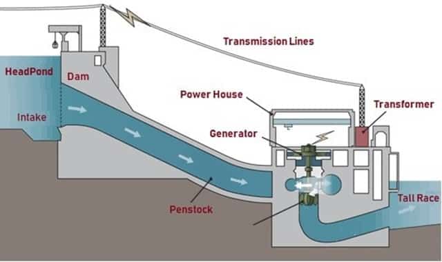
Layout of a hydroelectric power plant
Efficiency to Turbines
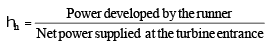
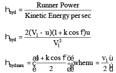
- Hydraulic efficiency (hh)

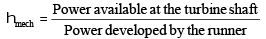
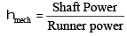
- Mechanical efficiency (hmech)
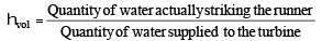
- Volumetric efficiency (hvol)
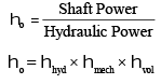
- Overall efficiency (ho)
Classification of Turbines on the basis of energy at inlet
- Impulse Turbines: These have only kinetic energy at inlet.
Example: Pelton Wheel, Gurard Turbine, Banki Turbine, Jonval Turbine, Turgo Impulse Wheel. - Reaction Turbines: These have kinetic energy and pressure energy both at inlet.
Example: Francis Turbine, Propeller Turbine, Kaplan Turbine, Thomson Turbine, Furneyron Turbine.
Classification of Turbines on the basis of type of flow within turbine
- Tangential Flow Turbine: Example: Pelton Wheel, Turgo Impulse Wheel.
- Radial Flow Turbines: Example: Inward-radial flow turbines are Francis turbine, Thomson Turbine, Guard Turbine. Outward-radial flow turbine is Fourneyron turbine
- Axial Flow Turbines: Example: Jonval Turbine, Propeller Turbine, Kaplan Turbine
- Mixed Flow Turbine: Example: Modern Francis Turbine
- Specific speed of turbines
Turbine Specific Speed (MKS Unit) |
Pelton Turbine 10 to 35 Francis Turbine 60 to 300 Kaplan & Propeller Turbine 300 to 1000 |
- Head of turbines
Turbine Head |
Pelton Turbine above 250 m Francis Turbine 60 m to 250 m Kaplan & Propeller Turbine Below 60 m |
Pelton Turbine
- It is tangential flow impulse turbine.
- It is high head low discharge turbine.
- The bucket of a pelton wheel is double semi-ellipsoidal in shape. The jet of water impinges at the centre of the bucket & deflects through 160-170°, (The deflection angle is 160° to 170°).
- The advantage of having double cup-shaped buckets is that the axial thrust neutralizes each other. A notch is cut at lower tip of bucket, which prevents the jet striking the preceding bucket and avoid the deflection of water towards the centre of bucket.
- Theoretically six jets can be used with one pelton wheel but practically not more than two jets for a vertical runner and not more than four jets for horizontal runner should be used.
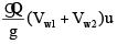
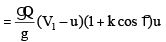
- Work done per second =
V1 = Velocity of jet coming out of nozzle
u1 = u2 = u = tangential velocity of vane
k = Bucket friction coefficient
Efficiency of Pelton wheel
(i) Nozzle efficiency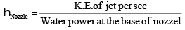
(ii) Hydraulic efficiency
(iii) Mechanical efficiency
(iv) Overall efficiency
ho = hN × hh × hmech
- Velocity of jet, V 1
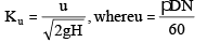
Cv = coeff of velocity = 0.97 – 0.99 - Speed Ratio
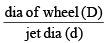
Ku = 0.43 – 0.47 - Jet ratio (m) =
A jet ratio of 12 is normally adopted - No. of Buckets (Z) =
This formula is called Tygun formula. - If P is power developed by the pelton wheel when working under head (H) & having one jet only, the power developed by the same wheel will be (n. P) in n jets are used under the same head.

Francis Turbine
- It is inward radial flow reaction turbine.
- Scroll casing is used to evenly distribute the water along the periphery & maintaining the constant velocity for the water
- Draft Tube - The water after passing through the runner flows to the tail race through a draft tube which is a passage of gradually increasing cross-section area which connects the runner exit to tail race. The basic function of draft tube is to convert kinetic head into the pressure head.
Purpose of draft tube
(i) Permits the negative suction head to establish at the runner exit
(ii) It acts as a recuperator of pressure energy.
The angle of straight divergent type draft tube should not be more than 8° otherwise eddies will be formed & efficiency will be reduced.
- Inward Flow reaction turbine
- Work done per sec
- For best efficiency flow should be radial at outlet,
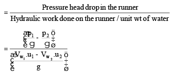
i.e., work done per sec - Degree of reaction
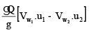


V & V are whirl velocities at inlet and outlet u1 & u2 are peripheral velocities of blades at inlet and outlet.
- Flow ratio = = 0.15 0.30
- Speed ratio = = 0.60 0.90
- Discharge through the turbine
Q = pD1 B1 Vf4
= pD2 B2 Vf2
B1, B2 are width of inlet & outlet
D1, D2 are diameter at inlet & outlet
Vf4 , Vf2are velocities of flow at inlet & outlet
 = 0.15 0.30
 = 0.60 0.90
Kaplan Turbine
- It is axial flow reaction turbine.
- Runner of kaplan turbine has four to six blades.
- Runner blades of propeller turbines are fixed but of kaplan turbine can be turned about axis.
- At part load, high efficiency can be obtained in kaplan Turbine.
- No. of blades are 3 to 6
- If frictional resistance is ignored, then Vr1 = Vr2
- Velocity of flow remains constant.
- Its velocity triangle & calculation of efficiency is similar to Francis turbine.
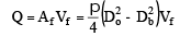
- Discharge through the turbine
- Flow ratio = y = 0.70
- Usually = 0.35 to 0.61
u1 = u2 =
Do = outer diameter of runner
Db = inner diameter or diameter of boss or hub
 = 0.35 to 0.61
Diagonal Turbine
- This is intermediate between the mixed flow and axial flow turbine because the flow of water as it passes through the runner is at an angle of 45° to the axis and hence is known as diagonal turbine.
- Head range is 30 m to 150 m
- Blades are adjustable.
- It can be used as turbine as well as pump.
Tubular Turbine
- Adjustable or non-adjustable runner blades.
- Head range 3 m to 15 m.
- Scroll casing is not provided.
- Runaway speed For a turbine working under maximum head & full gate opening, if the external load suddenly drops to almost zero value and at the same time, governing mechanism fail, turbine runner will tend to race up and attains maximum possible speed. This limiting speed of turbine is known as runaway speed.
For Pelton Turbine, Runaway speed is 1.8-1.9 times of normal speed.
For Francis Turbine, Runaway speed is 2-2.2 times of normal speed
For Kaplan Turbine, Runaway speed is 2.5-3 times of normal speed - Performance of Turbines/Unit Quantities The concept of unit quantities is required to (i) predict the behaviour of turbines working under different conditions. (ii) make comparison between the same type but different size of turbines.
(iii) co-relation and use of experimental data.
- Unit speed, Nu =
- Unit discharge, Qu =
- Unit power,
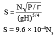
- Specific speed (Ns) of any turbines is the speed in rpm of a turbine, geometrically similar to the actual turbine but of such a size that under corresponding conditions it will develop unit power when working under unit head.
Note that specific speed is not a dimensions parameter, its unit is [M1/2L–1/4T–5/2] - Dimensionless form of specific speed is called shape number (S).
- Model Laws of Turbines
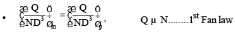
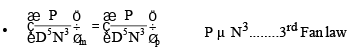
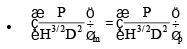
The parameter
is called flow coefficient. or capacites co-efficient.
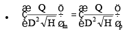
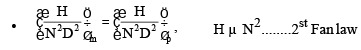
The parameter
is called head coefficient.
The parameter
is called power coefficient.
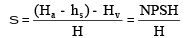
Note: Similarity of model and prototype turbines are based on the assumption that efficiency of model is equal to that of the prototype. But the efficiency of prototype is higher than the models efficiency. This is known as scale effect. - Thoma’s cavitation factor (s)
Ha = Atmospheric head
Hv = Vapour pressure head
hs = Suction head (at the outlet of reaction turbine)
H = Working head
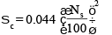
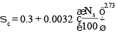
NPSH = Net Positive Suction Head - Critical value of Thoma’s number (sc) depends upon Ns and is given by:
(a) For Francis Turbine,
(b) For Propeller Turbine,
(c) For Kaplan Turbine, sc is 10% higher than sc for properller turbine. - Condition for no cavitation


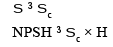
|
5 videos|103 docs|59 tests
|
FAQs on Hydraulic Turbines - Mechanical Engineering SSC JE (Technical)
| 1. What is a hydraulic turbine? |  |
| 2. How does a hydraulic turbine work? | |
| 3. What are the different types of hydraulic turbines? | |
| 4. What are the advantages of using hydraulic turbines for power generation? | |
| 5. Are there any environmental considerations associated with hydraulic turbines? | |

|
1.7K Views |

|
4.97/5 Rating |

|
Dec 26, 2024 Last updated |
|
5 videos|103 docs|59 tests
|

|
Explore Courses for Mechanical Engineering exam
|
|
ppt
,Hydraulic Turbines | Mechanical Engineering SSC JE (Technical)
,study material
,Hydraulic Turbines | Mechanical Engineering SSC JE (Technical)
,practice quizzes
,Important questions
,video lectures
,Viva Questions
,past year papers
,mock tests for examination
,Objective type Questions
,Exam
,Previous Year Questions with Solutions
,Summary
,Hydraulic Turbines | Mechanical Engineering SSC JE (Technical)
,MCQs
,Semester Notes
,Extra Questions
,shortcuts and tricks
,Free
,Sample Paper
;


Hydraulic Turbines Free PDF Download
Importance of Hydraulic Turbines
Hydraulic Turbines Notes
Hydraulic Turbines Mechanical Engineering Questions
Study Hydraulic Turbines on the App
|
© EduRev
|
Education Revolution
|


|


