Combustion in SI & CI Engine | Mechanical Engineering SSC JE (Technical) PDF Download
| Table of contents |
|
| Combustion in SI And CI Engine |
|
| Combustion with and without knocking |
|
| Stages of Combustion |
|
| Knocking in CI engine |
|

Combustion in SI And CI Engine
Combustion is the chemical reaction between fuel (hydrocarbon) and oxygen to liberate energy
• For petrol, chemically correct fuel air ratio or stoichiometric ratio is 1 : 15
• The ignition limit for petrol:
• minimum fuel air ratio = 1 : 30
• maximum fuel air ratio = 1 : 7
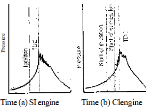
Stages of Combustion in SI Engine
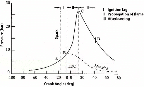
- Stage I - Ignition lag
The time lag between first igniting of fuel and the commencement of main phase of combusition is called ignition lag. It is preparation phase for flame propagation.
- Stage II - Flame propagation
Due to turbulence, the flame fastly travels most of the length of the cylinder it is flame propagation its start is the point of sudden rise of pressure in the cylinder. - Stage III - After burning
It is the after burning phase in which the remaining fuel particles start burning as soon as they come into contact with the air particles.
Effect of Engine Variables on Ignition Lag
Parameter increased | Effect on ignition lag |
Self ignition temperature | Increases |
Initial temperatureand pressure | Decreases |
Turbulance | Increases |
Compression ratio | Decreases |
Speed | Increases |
Advancingspark | Decreases |
Effect of Engine Variables on Flame Propagation
Parameter increased | Effect on flame propagation (Flamespeed) |
Compression ratio | Increases |
Initial temperature and pressure | Increases |
Engine load | Increases |
Turbulance (not excessive ) | Increases |
Speed | Increases |
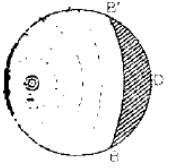
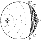
Flame propagation Flame propagation
before self ignition after self ignition
Combustion with and without knocking
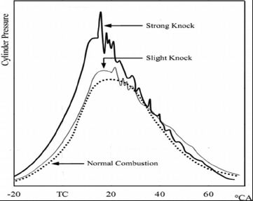
Detonation or Knocking
- If before flame reaches last unburnt mixture the mixture auto ignites because of high temperature, this is called knocking. At high temperature the mixture require some time to autoignite. This time is ignition delay. Knocking causes severe pressure wave which sets the engine vibrating.
Effect of Engine Variables on Knocking
Parameterincrease | Tendency of knocking |
Compression ratio | Increases |
Super ch arging | Increases |
Intel temperatureand pressure | Increases |
Engineload | Increases |
Advancingspark | Increases |
Turbulance | Decreases |
Speed | Decreases |
Oc tane number | Decreases |
Length of carbon chain | Increases |
- For 10% richer mixture than stoichiometric knocking is maximum. As the mixture is made leaner or richer than this, knocking tendency decreases.
Surface Ignition
- It is the initiation of a flame front by a hot surface not by the spark. The hot surface may be spark plug, electrode, exhaust valve head etc. This is mainly caused by carbon deposits.
Preignition
- If the surface ignition occurs before the passage of spark. It is called preignition.
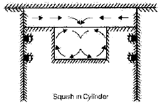
Squish
- Squish is the rapid ejection of gas trapped between the piston and cylinder head. It induces turbulence which decreases knocking tendency
Combustion Chamber Design Principle
- Large inlet valve to achieve high volumetric efficiency.
- High surface-volume ratio to reduce flame propagation time.
- Exhaust valve should be small and should not be in end region to prevent surface ignition. It should be near spark plug.
Type of Combustion Chambers
- T-Head combustion chamber
It is long combustion chamber which causes high knocking tendency. - L-Head combustion chamber
It is also called side valve combustion chamber. It is used for low compression ratio engine. - I-Head combustion chamber
It is also known as overhead valve combustion chamber. It is mainly used for high compression ratio. It has following properties-low surface to volume ratio, higher volumetric efficiency, less losses, less flame travel length etc.
- F-Head Combustion chamber
It possess almost all the requirements of combustion chamber viz. high volumetric efficiency, compression ratio and thermal efficiency.
CI ENGINES
- In CI engine air is compressed through a large compression ratio (12 : 1 to 22 : 1) during compression stroke raising its temperature to p ignition point. Then fuel is injected through fuel pump. So the air and fuel mix with each other and self ignite.
Stages of Combustion
I. Delay Period
- In CI engines the delay period is divided into physical delay and chemical delay. Physical delay is the time between start of injection and attainment of chemical reaction conditions. During this period fuel is atomized, vaporized and is mixed with air.
- Chemical delay for CI engines is the same as ignition delay for SI engines. During this phase reaction start slowly and ignition takes place.
II. Rapid or Uncontrolled combustion
- During the ignition delay period more and more fuel droplets come out of the injector and get collected in the combustion chamber. As soon as the delay period is completed these droplets start burning together. This produces uncontrolled or rapid combustion at the beginning of combustion in CI engines.
III. Controlled Combustion
- After some gap of time the temperature of combustion chamber is so high that as soon as the fuel droplets enter the combustion chamber, they start burning. Hence this phase is known as controlled combustion.
IV.After Burning
- This phase involves combustion of less volatile fuel particles which have not yet burnt. As soon as they come into contact with air particles they will start burning leading to after burning phase.
Effect of Variable on Delay Period
S.No | Increase in variable | Effect on delay Period | Reason |
1. | Cetane number of fuel | Reduces | Reduces self-ignition temperature |
2. | Injection Pressure | Reduces | Greater surface volume ratio hence less physical delay. |
3. | Injection advance angle | Increases | Pressures and temperatures lower when injection begins. |
4. | Compression ratio | Reduces | Increases air temperature and pressure and reduce auto-ignition temperature |
5. | Intake temperature | Reduces | Increases air temperatures |
6. | Jacket water temp | Reduces | Increases wall and hence air temperature |
7. | Fuel temperature | Reduces | Better vaporization and increases chemical reaction |
8. | Intake pressure (supercharging) | Reduces | Increase in density reduces auto-ignition temperature |
9. | Speed | Reduces in milliseconds, increases in crank angle | Less loss of heat more crank angle in a given ime |
10. | Load (fuel air-ratio) | decreases | Opening temperature increases |
11. | Engine size | Little effect in milli-seconds but crank angle decreases | Low rpm |
12. | Type of combustion chamber | lower for precombustion chamber |
Knocking in CI engine
- If the delay period is long a large amount of fuel will be collected in the combustion chamber before ignition starts. The auto-ignition of this large amount of fuel may cause high rate of pressure rise which causes knocking in diesel engines.
- All the factors which increases delay period are the cause of knocking in CI engine.
Comparison in Knocking Phenomenon of SI Engine and CI Engine
SI engine | CI engine |
Knocking occurs in the end of combustion | Knocking occurs in the begining of combustion |
Rate of pressure rise is very high due to homogeneous mixture | Rate of pressure rise is less due to hatrogeneous mixture |
Knocking occurs due toshort delay period | Knocking occursdue to long delay period |
Knocking is easily distinguis hible | Knocking is not easily distinguis hible |
- The factors that reduces knocking tendency in SI engine increases the knocking tendency in CI engine and vice versa. So to avoid knocking factors should be controlled as follows.
Factors | SI engine | CI engine |
Self ignition temperature | High | Long |
Delay period | Long | Short |
Compression ratio | Long | High |
Intel temperature | Long | High |
Speed | High | Long |
Oc tan ce number | High | Long |
Ce tan e number | Long | High |
Turbulence
- It is a disordered air motion in engine with no direction of flow to break flamenucleaus so as to induce flame propagation.
Swirl
- It is the orderly movement of air with a particular direction of flow to supply fresh air to burning droplet of fuel and wash away the products of combustion which otherwise would suffocate the burning droplet.
Squish
- It is the secondary air movement. It is the flow of air radially inwards towards the combustion recess by squeezing it out from between the piston and the cylinder head as they approach each other at the end of the stroke.
CI Engine Combustion Chamber
- The basic function of the combustion chamber in CI engine is to provide swirl to have better mixing of fuel air and proper combustion.
Induction swirl with open combustion chamber
- With multiple orifice injector and by directing the flow of the air during its entry to the cylinder, swirl is created in the combustion chamber.
- These are very useful for cold starting and large low speed engine. It is not good for variable speed range.
Compression swirl with divided combustion chamber
- With single pintle injector (due to self cleaning property of the injector) and by forcing the air through a tangential passage into a separate swirl chamber during the compression stroke, swirl is created. This type of combustion chamber is compression swirl with divided combustion chamber. This is very useful for variable speed operation and has higher volumetric efficiency. Cold starting is problem in it and it is costly.
Pre combustion chamber
- In this, the turbulence is created by combustion of small amount of fuel in a prechamber. Here single hole pintle type of nozzle is used. It has multifuel capability. The main disadvantage is the heat loss.
Glow Plug
- It is an electric heater which is used to heat the combustion chamber before the starting of engine.
|
5 videos|103 docs|59 tests
|
FAQs on Combustion in SI & CI Engine - Mechanical Engineering SSC JE (Technical)
| 1. What is the difference between combustion in SI and CI engines? |  |
| 2. What is knocking in combustion and how does it affect engine performance? | |
| 3. What are the stages of combustion in an engine? | |
| 4. How does combustion differ when knocking occurs in a CI engine? | |
| 5. How can knocking be prevented in combustion engines? | |


Combustion in SI & CI Engine | Mechanical Engineering SSC JE (Technical)
,Viva Questions
,Objective type Questions
,Exam
,Extra Questions
,Previous Year Questions with Solutions
,video lectures
,Semester Notes
,Combustion in SI & CI Engine | Mechanical Engineering SSC JE (Technical)
,ppt
,mock tests for examination
,practice quizzes
,shortcuts and tricks
,Summary
,Free
,MCQs
,Combustion in SI & CI Engine | Mechanical Engineering SSC JE (Technical)
,Important questions
,study material
,past year papers
,Sample Paper
;


Combustion in SI & CI Engine Free PDF Download
Importance of Combustion in SI & CI Engine
Combustion in SI & CI Engine Notes
Combustion in SI & CI Engine Mechanical Engineering Questions
Study Combustion in SI & CI Engine on the App
|
© EduRev
|
Education Revolution
|


|


