Gears | Mechanical Engineering SSC JE (Technical) PDF Download

GEARS
NTRODUCTION
Gears uses no intermediate link or connector and transmit the motion by direct contact. The two bodies have either a rolling or a sliding motion along the tangent at the point of contact. But under sliding or slipping they are called rollers and under no slidding or sliping they are called grears. No motion is possible along the common normal as that will either break the contact or one body will tend to penetrate into the other.
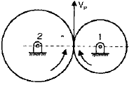
Point P can be assumed on gear 2 or gear 1.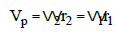

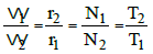
Symbols has usual meaning
CLASSIFICATION OF GEARS BASED OF THE ARRANGEMENT OF SHAFT
1. Parallel shaft
A. Spur Gears : They have straight teeth and parallel to the axis of rotation and thus are not subjected to axial thrust due to tooth load.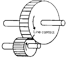
| Points to Remember : At the time of engagement of the two gears, the contact extends across the entire width on a line parallel to the axis of rotation. This results in sudden application of the load, high impact stresses and excessive noise at high speeds. |
B. Spur Rack and Pinion : Spur rack is a special case of spur gear where it is made of infinite diameter so that the pith surface is plane. Here rotary motion is converted into translatory motion or vice-versa. It is used in lathe in which the rack transmits motion to the saddle.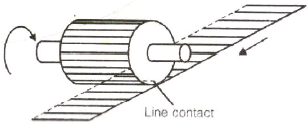
C. Helical gears or Helical spur gears:- In helical gears, the teeth are straight but inclined to axis of rotation. Two mating gears have the same helix angle but have teeth of opposite lands.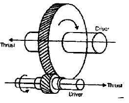
Points to Remember :
|
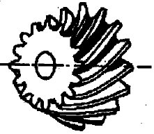
D. Double-helical and Herring bone Gears : A double-helical gear is equivalent of a pair of helical gears secured together one having a right hand helix and other a left hand helix.
Points to Remember :
|
2. Intersecting Shaft
The motion between two intersecting shafts is equivalent to the rolling of two cones assuming no slipping.
A. Straight bevel Gears: The teeth are Straight, radial to the point of intersection of the shaft axis and are tapered in cross-section throughout their length.
| Points to Remember : Gears of the same size and connecting two shafts at right angle to each other are known as mitre gears. |
B. Spiral bevel Gears: When the teeth of a bevel gear are inclined at angle to the face of the bevel, they are known as spiral bevel or helical bevels.
Points to Remember
|
- Zero bevel Gears: Spiral bevel gears with curved teeth but with a zero degree spiral angle are known as zero bevel gears.
3. Skew Shaft
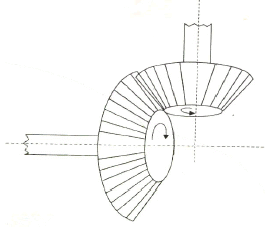
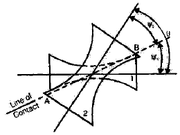
- In case of skew (non-parallel, non-intersecting) shafts, a uniform rotary motion is not possible by pure rolling contact.
- If it is desired that the two hyperboloids touch each other on the entire length as they roll, they must have some sliding motion parallel to the line of contact.
- If the two hyperboloids rotate on their respective axes, the motion between them would be a combination of rolling and sliding action.
- Angle between two shafts will be equal to the sum of the angles of generation of two hyperboloids.
q=y1+y2
A. Crossed helical gears
- The use of crossed-helical gear or spiral gears is limited to light loads. These gears are used to drive feed mechanism in machine tools, camshafts and oil pumps in I.C. engine .
B. Worm Gears
- It is a special case of a spiral gear in which the larger wheel usually has a hallow or concave shape.
- The smaller of the two wheels is called the worm which also has a large spiral angle.
- The sliding velocity of a worm gear is higher as compared to other types of gears.
- In Non-throated worm gear the contact between the teeth is concentrated at a point.
- In single throated worm gear, there is area contact between the teeth.
- A worm may be cut with a single or multiple thread cutter.
C. Hypoid Gear
- A hypoid pinion is larger and stronger than a spiral bevel pinion.
- A hypoid pair has a quite and smooth action
- There is continuous pitch line contact of the mating hypoid gear while in action and they have larger number of teeth in contact than straight tooth bevel gears.
GEAR TERMINOLOGY
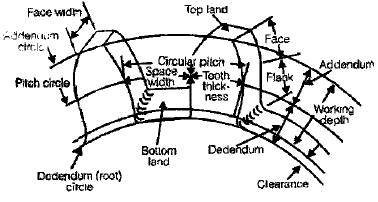
Pitch Circle : It is an imaginary circle drawn in such a way that a pure rolling motion on this circle gives the motion which is exactly similar to the gear motion.
Points to Remember :
|
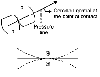
- Pitch point: It is a point where the two pitch circle of the mating gear touch each others.
- Pressure angle (φ): It is the angle between common normal at a point of contact tangent at a pitch point.
The standard value of pressure angle are  ,20º,25º.
- Module (m): It is defined as the ratio of pitch circle diameter in mm to the number of teeth.
m = D(mm)/T
- Addendum Circle: A circle drawn from top of tooth and concentric to pitch circle is known as addendum circle. Addendum is Radial distance between pitch circle and addendum circle and it is equal to 1 module.
NOTE:Clearance = 0.157 m
- Dedendum Circle: A circle drawn from bottom of the teeth and concentric with pitch circle. Dedendum is Radial distance between pitch circle and dedendum circle and it is equal to 1.157 module.
- Circular Pitch (C): It is a distance along a pitch circle from one point on a tooth to the corresponding point on the next tooth.

D = Pitch circle diameter
T = Number of Teeth
- Diametral Pitch: It is the ratio of number of teeth to the pitch circle diameter but diameter should be in mm.

- Relation between circular pitch (C) diametral pitch (pd)
Circular pitch × Diametral pitch = π
- Tooth Thickness : It is the thickness of tooth measured along pitch circle.
- Tooth Space: The space between the consecutive teeth measured along the pitch circle.
- Backlash: It is difference between tooth space and tooth thickness, which is generally provided to avoid jamming due to thermal expansion.
- Face: The portion of tooth profile above the pitch surface.
- Flank: The portion of tooth profile below the pitch surface.
- Profile: The curvature contained by face and flank.
- Path of contact (POC): It is the path travelled by point of contact from the starting of engagement to the end of engagement.
POC = path of approach + path of Recess.
- Arc of Contact (AOC): It is the path traced by a point on the pitch circle during starting of engagement to the end of engagement.
- Gear Ratio (G)
G = T/t
Here,
T = Number of teeth of gear.
t = Number of teeth of pinion (small gear).
- Velocity Ratio (VR)
VR = 1/ Gear ratio
- Angle of Action: Angle turned by gear from the beginning of engagement to the end of engagement of a pair of teeth. = Angle of approach + angle of recess
- Contact Ratio = Angle of action/Pitch angle = Arc of contact/circular pitch
LAW OF GEARING
- The law of gearing states the condition which must be fulfilled by the gear tooth profiles to maintain a constant angular velocity ratio between two gears.
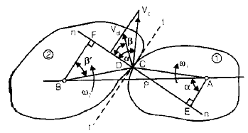
Let ω1 = angular velocity of gear 1 (clockwise)
ω2 =angular velocity of gear 2 (anti clockwise)
Condition:
(i) If it is desired that angular velocities of two gears remain constant, the common normal at the point of contact of the two teeth should always pass through a fixed point P which divides the line of centres in the inverse ratio of angular velocities of two gears.
(ii) For constant angular velocity ratio of the two gears, the common normal at the point of contact of the two mating teeth must pass through the pitch point.
- Velocity of Sliding
If the curved surfaces of the two teeth of the gears have to remain in contact one should have a sliding motion relative to the other along the common tangent.
Velocity of sliding = (ω1 + ω2) PC
= Sum of angular velocities X distance between the pitch point and point of contact.
TYPE OF TEETH PROFILE
(i) Cycloidal Profile Teeth
A Cycloid is the locus of a point on the circumference of a circle that rolls without slipping on the circumference of another circle. In this type, the faces of the teeth are epicycloids and flanks the hypocycloids.
- An epicycloid is the locus of a point on the circumference of a circle that rolls without slipping outside circumference of another circle.
- An hypocycloid is the locus of a point on the circumference of a circle that rolls without slipping inside the circumference of another circle.
- A property of the hypocycloid is that at any instant, the line joining the generating point with the point of contact of the two circles is normal to the hypocycloid.
- Meshing of Teeth: During meshing of teeth, the face of a tooth on one gear is to mesh with the flank of another tooth on the other gear. Thus for proper meshing it is necessary that the diameter of the circle generation face of a tooth is the same as the diameter of the circle generating flank of the meshing tooth, the pitch circle being the same in the two cases.
- In case of cycloidal teeth. The pressure angle varies from the maximum at the beginning of engagement to zero when the point of contact coincides with pitch point P and then again increases to maximum in the reverse direction.
- If the centre distance between the two pitch circles varies, the point P is shifted and the speed of the driven gear would vary.
(ii) Involute Profile
Involute is a curve generated by point on a tangent which rolls on a circle without slipping. The involute profile on a gear will be generated through a generating circle and this generating circle is known as base circle. Its radius will not change in any condition for a gear.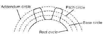
Points to Remember :
|
- For a pair of involute gears, velocity ratio is inversely proportional to the pitch circle diameters as well as base circle diameters.
- Path of Contact
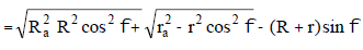
Here, r = Pitch circle radius of pinion
R = pitch circle radius of wheel
ra = addendum circle radius radius of pinion
Ra = addendum circle radius of wheel
- Arc of contact
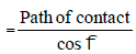
- Number of pairs of teeth in contact or contact ratio
= Arc of Contact / Circular Pitch
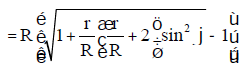
- The maximum value of the addendum radius of the wheel to avoid interference.
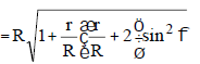
- Maximum value of addendum of the wheel
• Maximum number of teeth on the wheel for the given values of the gear ratio STUDENT CORNER
the pressure angle and the addendum coefficient (aw).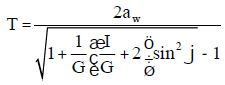
where aw = Addendum coefficient
NOTE:
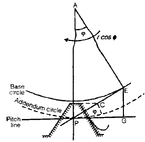
- Point of contact will always be at a line tangent to the base circle.
- Base circle diameter = pitch circle diameter X cos φ.
- For equal number of teeth on pinion and the wheel, G = 1
- To avoid interference, between rack and pinion the maximum addendum of the rack can be increased in such a way that C coincides with E.
Let the adopted value of the addendum of the rack be arm, where ar is the addendum coefficient.
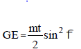

- To avoid interference, GE ³ arm
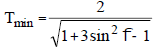
- For 20º pressure angle tmin = 13
CONDITION FOR INTERCHANGEABLE GEARS
The gears are inter changeable if they have
- the same module
- the same pressure angle
- the same addendums and dedendums, and
- the same thickness
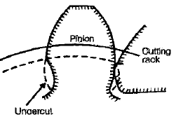
UNDERCUTTING
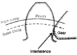
- If the addendum of the mating gear is more than the limiting value; it interferes with the dedendum of the pinion and the two gears are locked.
- If instead of the gear mating with the pinion, a cutting rack having similar teeth is used to cut, which would have interfered with the gear will be removed. A gear having its material removed in this manner is said to be undercut and the process undercutting.
COMPARISON OF CYCLOIDAL AND INVOLUTE PROFILE
Cycloidal Teeth
(a) Pressure angle varies from maximum at the beginning of engagement, reduces to zero at the pitch point and again increases to maximum at the end of engagement resulting in less smooth running of the gears.
(b) It involves double curve for the teeth, epicycloid and hypocycloid. This complicates the manufacture.
(c) Owing to difficulty of manufacture, these are costlier.
(d) Exact centre distance is required to transmit a constant velocity ratio.
(e) Phenomenon of interference does not occur at all,
(f) the teeth have wider flanks and thus are stronger
(g) In this a convex flank always has contact with a concave face resulting in less wear.
Involute Teeth
(a) Pressure angle is constant throughout the engagement of teeth. This results in smooth running of the gears.
(b) It involves single curve for the teeth resulting in simplicity of manufacturing and to tools.
(c) These are simple to manufacture and thus are cheaper.
(d) A little variation in the centre distance does not affect the velocity ratio.
(e) Interference can occur if the condition of minimum number of teeth on a gear is not followed
(f) The teeth have radial flanks and thus are weaker as compared to the cycloidal form for the same pitch
(g) Two convex surfaces are in contact and thus there is more wear.
HELICAL AND SPIRAL GEAR
In helical and spiral gear, the teeth are inclined to the axis of a gear. They can be right handed or left handed
Let, y1 = helix angle for gear 1
y2 = helix angle for gear 2
q = Angle between shaft
q = y1+ y2
(for gears of same hand)
q = y1 - y2
(for gears of opposite hand)
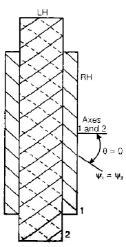
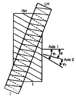
Angle between shafts, q=y1 - y2 , for gears of same hand
q = y1 - y2 , for gears of opposite hand
for y1 - y2 ,q=0 , a case of helical gears joining parallel shafts.
Terminology
- Helix angle ( y): It is the angle at which the teeth are inclined to the axis of rotation of a gear. It is also known as spiral angle.
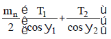
- Normal Circular (pn): Normal circular pitch or simply normal pitch is the shortest distance measured along the normal to the helix between corresponding points on the adjacent teeth. The normal circular pitch of two mating gears must be same.
Pn = P cos y
Also, we have, P = πm as for spur gear
Pn = πtmn
mn = m cos y
- Centre distance =
- Efficiency
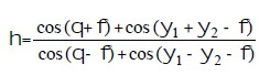
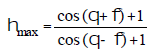
Here,φ = pressure angle
y = Helix angle
θ = Angle between two shaft
WORM AND WORM GEAR
- To accomplish large speed reduction in skew shaft spiral gears with a small driver and a larger follower are required.
- The load transmitted through these gears is limited.
- Usually worm and worm gears are used to connect two skew shafts at right angle to each other.
- A worm can be a single double or triple start it one, two or three threads are traversed on the worm for one tooth advancement of the gear wheel.
Terminology
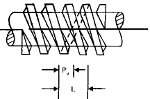
- Axial Pitch (Pa) is the distance between corresponding points on adjacent teeth measured along the direction of the axis.
- The distance by which a helix advances along the axis of the gear for one turn around is known as Lead (L).
- Lead angle (l) is the angle at which the teeth are inclined normal to the axis of rotation. The lead angle is the complement of the helix angle.
y+l= 90
- Velocity Ratio (VR)
= Angle turned by the gear / Angle turned by the worm
- Centre distance
- Efficiency
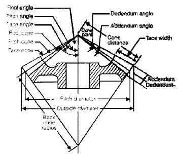
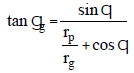
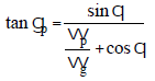
BEVEL GEAR
- To have a gear drive between two intersecting shafts, bevel gears are used.
Let, γg, γp = pitch angles of gear and pinion respectively
rg, rp = pitch radii of gear and pinion respectively.

|
5 videos|103 docs|59 tests
|
FAQs on Gears - Mechanical Engineering SSC JE (Technical)
| 1. What is mechanical engineering? |  |
| 2. What are gears used for in mechanical engineering? | |
| 3. What are the different types of gears used in mechanical engineering? | |
| 4. How are gears designed in mechanical engineering? | |
| 5. What are some common challenges in gear design and manufacturing? | |


MCQs
,video lectures
,Gears | Mechanical Engineering SSC JE (Technical)
,practice quizzes
,study material
,Gears | Mechanical Engineering SSC JE (Technical)
,ppt
,Viva Questions
,Gears | Mechanical Engineering SSC JE (Technical)
,Objective type Questions
,Important questions
,Extra Questions
,past year papers
,Semester Notes
,Summary
,Previous Year Questions with Solutions
,Exam
,mock tests for examination
,Sample Paper
,Free
,shortcuts and tricks
;


Gears Free PDF Download
Importance of Gears
Gears Notes
Gears Mechanical Engineering Questions
Study Gears on the App
|
© EduRev
|
Education Revolution
|


|


