Chapter - 3 Signals and Systems | Additional Study Material for Mechanical Engineering PDF Download
| Table of contents |

|
| 1. Introduction to Signals & Systems |

|
| 2. Linear Time Invariant (LTI) systems |

|
| 3. Fourier Representation of Signals |

|
| 4. Z-Transform |

|
| 5. Laplace Transform |

|
1. Introduction to Signals & Systems
Introduction: Signal is defined as a function that conveys useful information about the state or behaviour of a physical phenomenon. Signal is typically the variation with respect to an independent quantity like time.
System: System is defined as an entity which extracts useful information from the signal or processes the signal as per a specific function.
Classification of Signals
Continuous-Time vs Discrete-Time Signals: Continuous-time signal is defined as a signal which is defined for all instants of time. Discrete time Signal is a signal which is defined at specific instants of time only and is obtained by sampling a continuous - time signal. Also discrete-time signals are defined only at integer instants, is n ∈ z. Digital signal is obtained from discrete-time signal by quantization.
Conjugate Symmetric vs Skew Symmetric Signals: A continuous time signal x(t) is conjugate symmetric if x(t) = x'(-t);∀t. If x(t) = -x' (-t); ∀t. Also, x(t) is conjugate skew symmetric.
Any arbitrary signal x(t) can be considered to constitute 2 parts as below,
x(t) = xe(t)+ x0(t)
where xe(t) = conjugate symmetric part of signal =  and
and
x0(t) = conjugate skew symmetric part of signal = 
Periodic vs Non-Periodic Signals: A continuous -time signal is periodic if there exists T such that
x(t + T) = x(t), ∀t;T ∈ R - {0}
The smallest positive value of T that satisfies above condition is called fundamental period of x(t).
A discrete-time signal is periodic if there exists N such that
x[n] = x[n +N], ∀n; N ∈ Z - {0}
The smallest positive N that satisfies above condition is called fundamental period of x[n]. if x1(t) and x2(t) are periodic signals with periods T1 and T2 respectively, then x(t) = x1(t) + x2(t) is periodic iff (if and only if) T1/T2 is a rational number and period of x(t) is least common multiple (LCM) of T1 and T2. If x1[n] is periodic with fundamental period N and x2[n] is periodic with fundamental period M than x[n] = x1[n] + x2[n] is always periodic with fundamental period equal to the least common multiple (LCM) of M and N.
Energy & Power Signals: The formulas for calculation of energy E and power, P of a continuous/discrete-time signal are given in table below,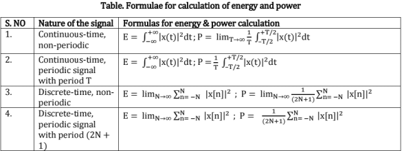
Characteristics of systems
Linearity: A system is linear if it satisfies superposition principle; i.e, weighted sum of inputs when given to a system should give a weighted sum of outputs. In general, for continuous time systems,
Time-Invariance: A system is time-invariant if delayed version of input leads to a delayed version of output by the same amount For continuous - time system to be time-invariant, y(t - T0) = T{x(t - T0)}.
Causality: A system is said to be causal if output at any instant depends upon past and present inputs only. A system is called anti-causal, if output at any instant depends on future inputs only. A system is called non-causal, if output at any instant depends upon future inputs also. From above anticausality implies non-causality, but the converse is not true.
Memoryless Property: A system is said to be memoryless if output at any instant depends on input at that instant, otherwise the system is said to have memory.
Stability: A system is said to be stable in bounded input bounded output sense if for any bounded input the system gives bounded output, otherwise system is unstable.
For continuous time signals, |x(t)| ≤ Bx < ∞ ⇒ |y(t)| ≤ By < ∞ for stability
Invertibility: A system is said to have inverse, if there exists another system so as to recover the original input from the output of first system.
2. Linear Time Invariant (LTI) systems
Convolution Sum: Any arbitrary signal x[n] can be described as, x[n] = 

Consider a discrete-time LTI system described as, y[n] = T{x[n]}
∴ For a LTI system, y[n] = x[n] x h[n] =  x[k] h[n-k] where h[n] is impulse response of the system.
Properties/Characterization of LTI System Using Impulse Response
Memoryless System: If system is memoryless, y[n] depends on only input at that instant,
∴ y[n] = h[0]. x[n] ⇒ hi[n] = C.δ[n] where C∈R
Causal System: If system is causal, y[n] depends on past and present inputs, x[m] (m≤n)
∴ h[n] = 0 for n<0, if system is causal.
Stable System:
∴ should be finite for BIBO stability.
Invertible LTI System: For a continuous time LTI system of impulse response, h(t) if there exists a impulse response hi(t) such that, h(t) x hi(t) = δ(t), then hi(t) is called inverse LTI system and h(t) is called invertible LTI system.
Representation of Continuous/Discrete-Time System
Transformation: Define a mapping related to input and output of system. y(t) = T{x(t)}
Representation of Continuous/Discrete-Time LTI System
Transformation: Define a mapping related to input and output of system.
Impulse response: Impulse response uniquely represents a LTl system
LCCDE (Linear Constant Coefficient Difference Equation): LCCDE represents the output at instant n, in terms of output and inputs.
System Function (H(eJω)/H(z))
From LCCDE, system functions H(eJω)/ H(z) can be derived as below.

Determining Impulse Response from Step Response: For a discrete-time LTl system, if yu[n] is unit step response, impulse response h[n] is given as, h[n] = yu[n] - yu[n - 1]
For a continuous-time LTl system, if yu(t) is unit step response, h(t) is given as,
Response of LTl System to Sinusoidal Input: Figure shown below gives the response of a discrete-time LTl system to a sinusoidal input.
Fig. Sinusoidal response of a discrete-time LTl system
The above relation implies that a LTl system produces a sinusoid in response to a sinusoid, the amplitude is multiplied by a factor |H(ejω)| and phase is changed by a factor arg(H(ejω)). The frequency response of a system gives information about how it affects sinusoidal input at a particular frequency.
3. Fourier Representation of Signals
Introduction: Here we represent signals as a linear combination of complex exponentials. The resulting representations are known as the continuous time and discrete time Fourier series and transform (depending on the nature of signal i.e. continuous/discrete and periodic/non periodic).
Fourier Representations: 
From the above table, we see that continuous-time signals have non-periodic frequency representation and discrete-time signals have periodic frequency representation. Also periodic signals have discrete frequency representation and non-periodic signals have frequency representation which is continuous in nature.
Fourier series (FS) for Continuous -Time Periodic Signals
Complex FS representation: Let x(t) be continuous -time periodic signal with period T,
 where T is period of x(t) and Ω0 = 2π/T
Alternate Fourier Series Representation: If f(x) is a signal of period 2T,
Here, is the dc component of f(x),
If f(x) is even,
lf f(x) is odd,
Discrete Time Fourier Series(DTFS): Let  is be discrete -time signal of period N,

 is also periodic with period N and is discrete in nature.
Fourier Transform (FT) for Continuous -Time Non-Periodic Signals: Let x(t) be a continuous-time non-periodic signal,
X(jΩ) is continuous with respect to fi and is non-periodic
The Fourier Transform X(jΩ) may not exist for all functions x(t). For the Fourier transform to exist, x(t) must satisfy the Dirchlet conditions given below,
- The signal x(t) must be absolutely integrable, i.e

- The signal x(t) must have finite number of local maxima and minima and discontinuities in any finite interval.
- The size of each discontinuity must be finite.
Discrete Time Non Periodic Signals; Discrete Time Fourier Transform (DTFT): Let x[n] be a discrete-time non-periodic signal,
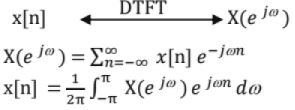
If the sequence, x[n] is absolutely summable, i.e.  then DTFT of the sequence, x[n] exists.
Properties of Fourier Representation
Symmetry Property - Real & Imaginary signals
If x(t) is real, Im(x(t)) = 0 and x(t) = Re (x(t)),
∴ x*(-jΩ) = X(jΩ)
∴ FT is conjugate symmetric ⇒ magnitude spectrum is symmetric.
If x(t) is imaginary, Re(x(t)) = 0 and x(t) = J lm(x(t))
∴ x *(-jΩ) = -X(JΩ)
∴ FT is conjugate skew-symmetric⇒ magnitude spectrum is symmetric.
If x(t) is conjugate symmetric,
x*(-t) = -x(t)
∴ FT is real ⇒ 
If x(t) is conjugate anti-symmetric
x*(-t) = x(t)
∴ FT is imaginary ⇒ 

Scaling Property:

- Linear scaling in domain corresponds to a linear scaling in frequency domain.
- Whenever a signal is compressed in time domain (a>l), it leads to expansion in frequency and vice versa.
Convolution Property: For continuous-time signals,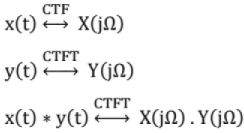
Convolution in time domain results in multiplication in frequency domain.
Parseval Theorem: Energy or power in the time domain representation is equal to energy or power in frequency domain representation.
4. Z-Transform
Introduction: ZT is a generalization of frequency response for discrete-time signals.
Two sided ZT/Bilateral ZT, X(z) = 
One sided ZT/Unilateral ZT, X(z) = 
For |z| = 1 or z = eJω, ZT is equal to DTFT. Therefore ZT evaluated along unit circle reduces to DTFT. For any given sequence, the set of values of Z for which the Z transform converges is called the region of convergence (ROC).
Rational Representation of Z.T. (X(z)): Consider the class of Z transform where in X(z) can be expressed as, where P(z) is numerator polynomial and Q(z) is denominator polynomial
Values of z for which P(z)=G are called the zeroes of X(z).Values of z for which Q(z) = 0 are called the poles of X(z). Location of poles of X(z) is related to the ROC and ROC is bounded by poles. To uniquely specify a discrete time signal, one needs to specify both X(z) and ROC.
From above we see that two different signals x1[n] and x2[n] have same Z-transform but different ROCs.
Properties of ROC
(1) ROC of X(z) consists of a ring in the z-plane centered about the origin.
(2) ROC does not contain any poles, but is bounded by poles.
(3) If x[n] is a finite duration sequence, then ROC is the entire z plane except possibly z = 0 or z = ∞.
(4) If x1[n] is a right sided sequence, then ROC extends outward from the outermost pole to possibly including z = ∞. As causal sequences are right sided, ROC of those sequences is outside a circle.
(5) If x2[n] is a left sided sequence, the ROC extends inward, from the innermost non-zero pole to possibly including z = 0. As anti-causal sequences are left sided, ROC of those sequences is inside a circle.
(6) If x3[n] is two sided sequence, the ROC will consist of a ring in the z plane bounded on the interior and exterior by a pole.
(7) lf x[n] is a finite duration sequence, ROC is entire z-plane except possibly z = 0 or z = ∞.
Properties of Z Transform
Linearity:
ROC in the current case is at least (R1 ∩ R2). If there is no poles—zero cancellation, ROC will be (R1 ∩ R2). If there is a pole-zero cancellation, ROC may be more than (R1 ∩ R2). If R1 ∩ R2 = ∅, then Z{ax1[n] + bx2[n]} doesn't exist.
Time Shifting: 
If no>0, ROC is R except z = 0. If n0< 0, ROC is R except z = ∞.
Modulation: 
If |a| >1, Z transform gets shrinked in Z-domain and vice versa. If a = Multiplication in time domain by an = eJω°n results in frequency shift in frequency domain by ω0.
Differentiation in Z- domain:
Conjugate property:
Time Reversal property:
Convolution property:
Initial Value Theorem:
x[0] = limz→∞X(z)
If X(z) is expressed as ratio of polynomials P(z) and Q(z), order of P(z) should be less than that of Q{z) for initial value theorem to be applied to X(z).
Final Value Theorem:
Necessary condition for applying final value theorem is that poles of (1 - z-1) X(z) should be strictly inside the unit cycle.
Characterization of LTI System from H(z) and ROC
A LTI system can be characterized for causality stability and memoryless properties based on ROC of the system function, H(z).
- If ROC includes unit circle, then system is stable.
- If ROC is outside a circle, then system is causal.
- If ROC is inside a circle, then system is anti-causal.
- If ROC is all z, then system is memoryless.
- If ROC is strictly a ring, then system is non-causal.
- If ROC includes unit-circle, then the system's impulse response is absolutely summable and hence DTFT of the sequence exists.
Finding Inverse Z.T. given X(z) and ROC
By Inspection and Partial Fraction: Given X(z) in rational form, split it into partial fractions and based on ROC, find x[n] by inspection.
By Division: Given X(z) in rational form, perform the division based on the condition that x[n] is causal or anti-causal and find X(z) in expansion form.
By Power Series Expansion: Given X(z) in a standard form, find the expansion of X(z}, then x[n]
5. Laplace Transform
Introduction: Laplace Transform (LT) is a method to get generalized frequency domain representation of a continuous - time signal and is generalization of CTFT (Continuous Time Fourier Transform).
Definition of Laplace Transform: One sided/ unilateral LT where S = (σ + Jω)
 Two sided/ bilateral LT
Properties of Laplace transform
Frequency shift:
Time shift:
Differentiation in Time domain: s F(s) - f(0) where f(0) is initial value of f(t).
If initial conditions are zero (i.e, f(0) = 0),differentiating in time domain is equivalent to multiplying by s in frequency domain.
Similarly,  =s2 F(s) - s f(0) - f'(0) where f'(0) is the value of
Integration in Time Domain:
Integration in time domain is equivalent to division by s in frequency domain, if f(t) = 0 for t < 0.
Differentiation in frequency Domain:
Differentiation in frequency domain is equal to multiplication by t in time domain.
Integration in Frequency Domain:
Integration in frequency domain is equal to division by t in time domain.
Initial Value Theorem: If f(t) and its derivative f'(t) are Laplace transformable, then
limt→0 f(t) = lims→∞sF(s)
This theorem does not apply to the rational function F(s) in which the order of numerator polynomial is equal to or greater than the order of denominator polynomial.
Final Value Theorem: If f(t) and its derivative f(t) are Laplace transformable, then limt→∞ f(t) = lims→0 s F(s)
For applying final value theorem, it is required that all the poles of sF(s) be in the left half of s- plane (strictly) i.e. poles on jω axis also not allowed.
Convolution theorem:
Laplace transform of the periodic function: If f(t) is periodic function with period T, then
Laplace transform of standard functions: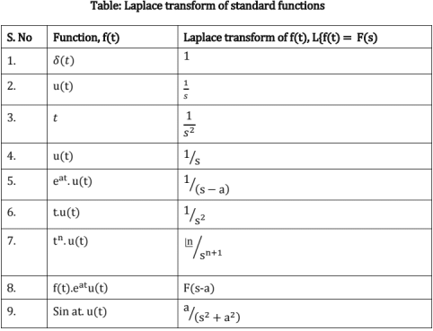
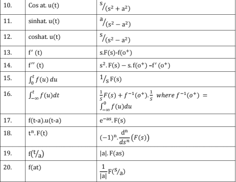
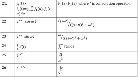
Applications:
- LT is generalization of CTFT for continuous-time signals and hence signal can be characterized at any generalized frequency.
- LT is helpful to perform transient and steady state analysis of any LTI system for any arbitrary input and initial conditions.
6. Frequency response of LTI systems and Diversified Topics
Frequency response of a LIT system
Consider a LTI system of impulse response h[n] as shown in figure below. For any arbitrary input x[n], output y[n] can be found by convolution, as below,
y[n]= x[n] * h[n]
If F{x[n]} = X(eJω) and Z{x[nj} = X(z),
Y(eJω) = H(eJω)).X(eJω) and Y(z) = H(z).X(z)
Here H(eJω) is called transfer function of LTI system and H(z) is called system function.
Amplitude Response: Plot of M = |H(eJω)| with respect to ω is called the amplitude response. It gives an idea about frequency content of the signal and can be used to characterize the system.
Phase Response: Plot of  with respect to ω is called the phase response. Similar to magnitude response, this can also be used to characterize the system.
Group Delay Response: Plot of G(ω) = -d∅/dω with respect to ω is called the group delay response.
Minimum Phase System: Minimum phase system is the system for which phase variation and energy variation are minimum with respect to ω. Also if minimum phase system is causal, poles and zeroes are inside the unit circle.
Linear Phase System: The system for which phase variation with respect to to is linear is called "linear phase system". If H(eJω) is a linear phase system,  and hence ∅(ω) = Aω + B. Also group delay is constant for linear phase system. For a linear phase system with real impulse response, zeroes form complex conjugate reciprocal pairs. So if there is zero at 'a' for linear phase system, then other zeroes are at a*, 1/a and 1/a*. For a linear phase system with complex impulse response, if there is a zero at a, then it's assured that there is a zero at 1/a*.
All - pass system: System which passes all the frequencies is called all-pass system
∴ |H(eJω)| = K; ∀ω where K is a constant.
For a all-pass filter, system function can be generalized as
For a all-pass system, poles and zeroes form a conjugate reciprocal pairs. Therefore for a all-pass system with complex impulse response, if there is zero at 'a', then there is a pole at 1/a* and vice versa. For an all-pass system with real impulse response, if there is a zero at a, then there is a zero at a* and there are poles at 1/a* and 1/a.
Magnitude transfer function: A system function C(z) is called magnitude transfer function, if it's of form, C(z) = H(z).H*(1/z*)
Therefore, for magnitude transfer function, poles form conjugate reciprocal pairs. Hence if there is a pole at 'a', there is a pole at 1/a*. Same applies for zeroes also.
Sampling: To get discrete-time signal from analog signal, sampling is performed on analog signal. Let x(t) be analog signal & S(t) be impulse train,
∴  where T is desired sampling interval
Sampled signal, xs (t) = x(t) . s(t) = 

After sampling, signal obtained above is still in time-domain. To get FT in discrete -time domain, put ω = ΩT, which is called time normalization
From above we see that X(eJω) is periodic with period 2π. To avoid aliasing, there should not be any intervention between frequency bands.
∴ Ωs - ΩN ≥ ΩN where ΩN is signal 13W ⇒ Ωs > 2ΩN to avoid aliasing (Nyquist sampling theorem)
As X(eJω) is periodic, DTFT is described as one period of CTFT, if there is no aliasing.
To get xr(t) from x[n], use low pass filter of impulse response hr(t) = sin c(t/T) as in figure below.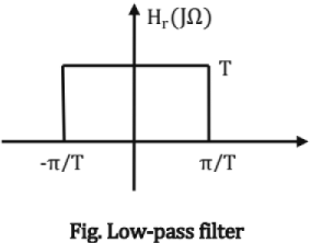

Discrete Fourier Transform (DFT): DFT is a sampled version of DTFT of a non-periodic signal x[n] in the range of (-π, π). This is mainly required for processing by computers. Consider a signal x[n] of length NP then its DFT, X[k] is given as,
Also, DFT is obtained by sampling DTFT with a period of 2π/N
Fast Fourier Transform (FFT): For evaluating DFT of x[n], number of multiplications and additions required are 0(N2). To reduce the computational complexity, another implementation of DFT is used, which is called Fast Fourier Transform (FFT). Number of multiplications required for FFT is 0(N.log2 N). FFT uses butterfly architecture with in place computation to save the processing time and memory requirements.
Filters: Filters are typically used to extract any useful information from a signal or to process a signal.
FIR Filters: Here output at any instant n, depends on only input and impulse response of FIR filter has finite length.
IIR Filter: Here output at any instant n, depends on input and past/future output and impulse response of HR Filter has infinite length.
Correlation and Covariance: If xn is a real and stationary signal, then auto-correlation and covariance functions can be defined as below,
Auto-correlation function, Rx[m] = E{xn+m-xn}
Auto-covariance function, Cx[m] = E {(x n+m - mx). (xn - mx)}
Here mx = E{xn} and xn+m is advanced version of xn by m samples.
Power spectral density of x is given as Px(ejω) = F{Rx[n])
|
1 videos|30 docs|57 tests
|
|
1 videos|30 docs|57 tests
|

|
Explore Courses for Mechanical Engineering exam
|

|


