Shear Force & Bending Moment | Mechanical Engineering SSC JE (Technical) PDF Download
SHEAR FORCE AND BENDING MOMENT
SHEAR FORCE AND BENDING MOMENT
1. SHEAR FORCE at the cross- section of a beam may be defined as the unbalanced
vertical force to the right or left of the section.
2. BENDING MOMENT at the cross- section of a beam may be defined as the
algebraic sum of the moment of the forces, to the right or left of the section.
3. BEAM is a structural number subjected to transverse loads only.
4. BEAMS can be classified as :
a. Simply supported beam:
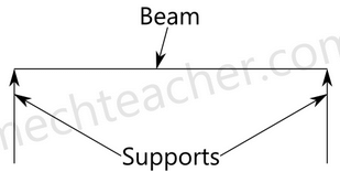
A simply supported beam is a type of beam that has pinned support at one end and roller support at the other end. Depending on the load applied, it undergoes shearing and bending. It is the one of the simplest structural elements in existence.
The following image illustrates a simply supported beam.
2. Cantilever beam:
A cantilever beam is fixed at one end and free at other end. It can be seen in the image below.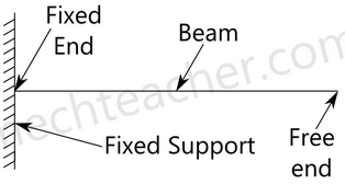
3. Overhanging beam:
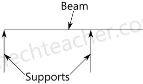
A overhanging beam is a beam that has one or both end portions extending beyond its supports. It may have any number of supports. If viewed in a different perspective, it appears as if it is has the features of simply supported beam and cantilever beam.
4. Continuous beam:
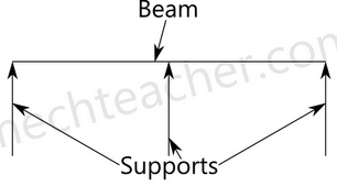
A continuous beam has more than two supports distributed throughout its length. It can be understood well from the image below.
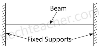
5. Fixed beam:
As the name suggests, fixed beam is a type of beam whose both ends are fixed.
5. Shear force and bending moment diagrams:
Sign Convention:
(i) Shear force
Positive Negative
SHEAR FORCE AND
5CHAPTER BENDING MOMENT
(ii) Bending moment STUDENT CORNER
Positive
(sagging
Nagative
(Hogging)
SFD and BMD for cantilever beams:
(i) Cantilever of length l carrying a concentrated load W at the free end
S x = + W
M x = – Wx
Mmax = – WL
(ii) Cantilever of length l carrying a uniformly distributed load of 'w' per unit run
over the whole length
Sx = + wx
Mx = –
wx2
2
Mmax = –
w 2
2
l
Smax = + wl
VA= Wl
Wl
w 2
2
l
BMD
(iii) Cantilever of length l carrying a uniformly distributed load of 'w' per unit run STUDENT CORNER
over the whole length and a concentrated load W at the free end
Sx = wx + W
Mx = –
wx2
wx
2
æ ö
ç + ÷
è ø
Smax = wl + W
Mmax = –
w 2
w
2
æ ö
ç + ÷
è ø
l
l
A
w per unit run
(iv) Cantilever of length l carrying a uniformly distributed load of 'w' per unit run for
a distance 'a' form free end
form D to B,
Sx = + wx
Mx = –
wx2
2
form A
Sx = + wa
Mx = –wa
x – a
2
æ ö
çè ø÷
W per unti run
M A D
l
B
e
v = wa
wa wa
B
w
D
D
A
A
Parabolic
Straight wa 1 a
2
æ ö
ç - ÷
è ø
(v) Cantilever of length 'l' carrying a load whose intensity varies uniformly from zero STUDENT CORNER
at free end to 'w' per unit run at the fixed end
Sx = +
wx2
2l
= area of load diagram between X and B, Smax = +
wl
2
Mx = Moment of load acting on XB about X
= area of the load diagram between X and
B × distance of centroid of this diagram
form X
= –
wx2 x
2 3
´
l
= –
wx3
6l
= Mmax =
w 2
6
l
A
A
V wl
2
=
wl
2
(vi) Cantilever carrying a load whose intensity varies uniformly form zero at the
fixed end to w per unit run at the free end
Sx =
w wx2 –
2 2
l
l
Mx =
w x wx2 w 2 – –
2 6 3
l l
l
STUDENT CORNER
3
2
6
wx
2
w 3 l 2
l
l - -
cubic
BMD
SFD and BMD for simply supported beams:
(i) Simply supported beam of span l carrying a concentrated load at mid span
Sx = +
W
2 (between AC)
Sx = –
W
2 (between CB)
Mx = +
W
2 x (between CB)
Mx = +
W
2 x (form A to C) (at a distance 'X' form A)
Mmax = Mc =
W
4
l
A
V w
2
= B
V w
2
=
(ii) Simply supported beam carrying a concentrated load placed eccentrically on STUDENT CORNER
the span
Sx = +
Wb
l
(form A to D)
= –
Wb
l
(form D to B)
Mx = +
Wb
l
x (form A to D)
at a distance 'x' form A
Mmax = MD =
Wab
l
A a
W
b B
D
B
SFD
D
BMD D B
A
l
A
V wb =
l B
V = wa
l
wab
l
w.a
l
w.b
l
NOTE: Maximum B.M. occurs where S.F. changes its sign.
(iii) Simply supported beam carrying a uniformly distributed load of w per unit run
over the whole span
Sx = +
W
2
l
-wx Mx =
W
2
l
x –
Wx2
2
, max
S WL
2
=
Mmax = Mc =
W 2
8
l
Va
2
l
l/2 l/2 wl2
8
(iv) Simply supported beam carrying a load whose intensity varies uniformly from STUDENT CORNER
zero at each end to 'w' per unit run at the mid span
2
x x w
4
S w
l
l = + -
Smax = +
W
4
l
Mx = 3 W W
x– x
4 3
l
l
Mmax =
M
c
=
W 2
12
l
+
12
wl2
2w x
l
w
4
V w b
l =
4
V w a
l
=
A
(v) Simply supported beam carrying a load whose intensity varies uniformly from
zero at one end to 'w' per unit run at the other end
Sx =
w wx2 –
6 2
l
l
Mx =
w wx3 x –
6 6
l
l
A
V wl
6
= b
V wl
3
=
wl
6
A B
STUDENT CORNER
Mmax B.M. occurs at x = 3
l
form end A
Mmax =
w 2
9 3
l
SFD and BMD for simply supported beams with overhang:
Simply supported beam with equal overhangs and carrying a uniformly
distributed load of 'w' per unit run over the whole length
S.F. at any section in EA at a distance x form E,
Sx = –wx
at any section in A.B,
Sx = ( ) w
2a – wx
2
l+
B.M. at any section in EA,
Mx = –
wx2
2
at any section in AB.
Mx = ( )( )
w wx2 l 2a x–a –
2 2
+
at x = 'a' and 'a + l' i.e., at A & B,
Mx = –
wa2
2
at x = a + i.e., atC
2
l
Mc = ( 2 2 ) w
– 4a
2
l
E
w unit per run
Cl
a a
A B D
C F
wa
D
a
A
o o o
D
E
E
n
V w(1 2a)
2
+
= n
V w(1 2a)
2
+
=
wl
2
wl
2
l2 4a2
2
-
wa2
2
wa2
2
wa
B
BMD
Case (a) : l2 > 4a2 Þ l > 2a STUDENT CORNER
l2 – 4a2 > 0 Þ Mc > 0 (Positive)
B.M.D. will be as shown in figure above of contraflexure O1 & O2 are at a
distance
2 4a2
2
1 = l - form centre.
Thus distance between point of contraflexure
O1 O2 = l2 - 4a2
Case (b) : l2 = 4a2 Þ p = 2a
B.M at C = Mc = 0
The beam will be subject to only hogging moments.
Points of contraflexure O1 & O2 will coincide with C.
B.M.D will be as shown in figure (a)
w per unit run
E
2
a wl
= l 2
a wl
=
V = w a l V = w b l
2
wl
2
wl
A
2
wl
2
wl
8
wl 2
8
wl 2
E
Case (c) l2 – 4a2 < 0 Þ l > 2a
E
wl
2
wl
E A
2
wl
2
wa2
2
wa2
BMD
(b)
(4a )
8
w 2 l2 -
C D
D
wa SFD
A C B
M STUDENT CORNER c is negative ,since l 2 < 4a2
Mc = – ( 2 2 ) w
4a –
8
l
B. M. will be zero only at ends A and D and at all other sections B.M. will be of
hogging type
B.M. and S.F due to a couple
Case (a): Cantilever
There will be no shear force
Case (b): Simple supported
Shear force is constant
Sx = –
M
l
B.M., Mx = –
Ma
l
(left of C)
= +
Mb
l
(right of C)
C
b
SFD
BMD
l
V M a = l
V M b =
A
l
Ma
l
Ma
l
Mb
l
Mb
A B
|
6 videos|104 docs|59 tests
|
FAQs on Shear Force & Bending Moment - Mechanical Engineering SSC JE (Technical)
| 1. What is shear force and bending moment in mechanical engineering? |  |
| 2. How are shear force and bending moment related? |  |
| 3. How can shear force and bending moment be calculated? |  |
| 4. What are the applications of shear force and bending moment analysis? |  |
| 5. What are the typical signs of shear force and bending moment in beams? |  |


