Flow Through Pipes | Mechanical Engineering SSC JE (Technical) PDF Download
FLOW THROUGH PIPES
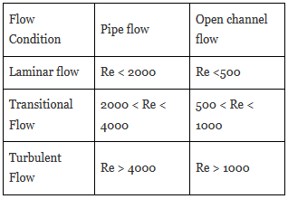
The limiting values of Reynold’s Number corresponding to which flow is Laminar is given by :
- Entrance length (Le) - The length of pipe from its entrance upto the point where flow attains fully developed velocity profile and which remains unaltered beyond that known as entrance length.
- The entrance length required to establish fully developed laminar flow is given by

- The entrance length for fully developed turbulent flow is given by

Losses in pipe flow
-It is often necessary to determine the head loss, hl , that occur in a pipe flow so that the energy equation, can be used in the analysis of pipe flow problems.
-The overall head loss for the pipe system consists of the head loss due to viscous effects in the straight pipes, termed the major loss and denoted hL-major.
-The head loss in various pipe components, termed the minor loss and denoted hL-minor.
That is ; hl = hL-major+ hL-minor
-The head loss designations of “major” and “minor” do not necessarily reflect the relative importance of each type of loss.
-For a pipe system that contains many components and a relatively short length of pipe, the minor loss may actually be larger than the major loss.
1. Minor losses
- Loss due to sudden expansion This loss is due to eddies in the corner and loss of momentum

he= (V12/2g)[1- (A1/A2)2]
V1 = Mean velocity before expansion
V2 = Mean velocity after expansion
A1 = Area of pipe before expansion
A2 = Area of pipe after expansion
- Loss due to sudden contraction This loss is due to eddies in vena contracta.
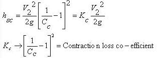
If value of Cc is not given, then the loss due to countraction is taken as 0.5
Where, V2 = velocity after contraction
Cc = Coefficient of contraction
Ac = Area of fluid at vena contracta
A2 = Area of pipe after contraction
- Exit loss

v → Mean velocity of flow in pipe
- Entry loss

- For sudden expansion, the optimum ratio of diameters of the pipe so that the pressure rise may be maximum

- Loss due to gradual expansion

hL = KL(V12/2g)[1- (A1/A2)2]
KL depends upon angle of expansion.
- Loss at pipe fittings


(2) Major losses
Darcy Weisbach equation.

f = Friction factor (0.02 to 0.04 for metals)
L = Length of pipe
D = Dia. of pipe
V = Mean velocity of flow
-It is valid for any fully developed, steady, incompressible pipe flow, whether the pipe is horizontal or on hill
-Friction factor for laminar flow is ;
f=64/Re
-Friction factor for turbulent flow is based on Moodychart.
-It is because, in turbulent flow, Reynolds number and relative roughness influence the friction.
-Reynolds number, Re=ρVD/μ
-Relative roughness = ε/D
(relative roughness is not present in the laminar flow)
-Friction loss in pipe whose end is closed and flow takes place through sides at regular interval

- Pipe Connections
- Series Connection :

(i) Discharge remains constant through all pipes.
(ii) Ignoring secondary losses the total loss of head is equal to the sum of the friction losses in the individual pipes.
- Parallel Connection
Pipes are said to be in parallel when they are so connected that the flow from a pipe branches or divides into two or more separate pipes and then reunite into a single pipe.
Suppose a main pipe branched at section 1-1 into two pipes of lengths l1 and l2 and diameters d1 and d2 and unite again at a section 2-2 to form a single pipe.
Then the two branch pipes are said to be connected in parallel.
In this arrangement the total discharge Q divides into components Q1 and Q2 along the branch pipes such that –
Q = Q1 + Q2
and in this arrangement the loss of head from section 1-1 to section 2-2 is equal to the loss of head in any one of the branch pipes.
hf = hf1 = hf2
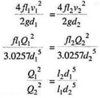
Hence the total discharge Q divides into components Q1 and Q2 satisfying the above equation.
-Power input to pump = g Q(H + hL)/h
-Power output in turbine = g Q(H – hL)h
-Power delivered by a given pipeline is maximum when the flow is such that one third of static head is consumed in pipe friction. Thus efficiency is limited to only 66.66%.
Siphon Action of Pipe
“In a piping system any part of the pipe is above the hydraulic gradient line it is called a siphon.”In Fig below shows a pipe in which the part BCD is above the hydraulic gradient line. The pressure head at any point along the axis of the pipe is equal to the distance between the HGL and the axis.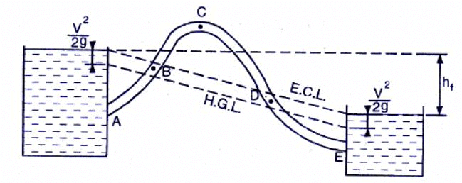
It shows that pressure head at points B and D is zero.The pressure head in the region BCD where pipe is above H.G.L. is negative. The minimum pressure would be at point C(summit point). If the absolute pressure at point C reache vapour pressure, gases, vapour bubbles are liberated and cavitation occurs.For water,the maximum height of summit above H.G.L. at normal temperature and pressure is 7.8 m.The discharge through a siphon may be calculated as

The siphon will start functioning only when it is primed, air is removed from it.
Uses of siphon
1.To carry away water from one reservoir to another reservoir separated by a hill orridge.
2.To take out the liquid from a tank which is not having any outlet.
3.To empty a channel not provided with any outlet sluice.
Water hammer in pipe
-Consider a long pipe AB as shown in Fig. below connected at one end to a tank containing water at a height of H from the centre of the pipe. At the other end of the pipe, a valve to regulate the flow of water is provided. When the valve is completely open, the water is flowing with a velocity, V in the pipe.
-If the valve is suddenly closed, the momentum of the flowing water will be destroyed and consequently a wave of high pressure will be set up. This wave of high pressure will be transmitted along the pipe with a velocity equal to the velocity of sound wave and may create noise called knocking. Also this wave of high pressure has the effect of hammering action on the walls of the pipe and hence it is known as water hammer.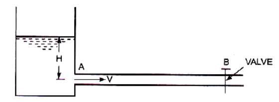
-The pressure rise due to water hammer depends upon: (i) the velocity of flow of water in pipe,(ii) length of pipe, (iii) time taken to close the valve, (iv) elastic properties of the material of the pipe. The following cases of water hammer in pipes will be considered:
1.Gradual closure of valve
2.Sudden closure of valve and considering pipe rigid
3.Sudden closure of valve and considering pipe elastic
-The valve closure is gradual if t > (2L/C)
-The valve closure is sudden if t < (2L/C)
where,
L = Length of pipe
t = time in sec.
C = velocity of pressure wave
(i) Gradual Closure
In this case the pressure head is given by
 where,L = Length of pipeV = Velocity of flow
t = time in second to close to close the valve.
(ii) Sudden Closure With Rigid Pipe
- The pressure head in this case is given by
 (Alliev formula) ... (II)
where,

V = Velocity of pressure wave
K = Bulk modulus of water
r = density of water.
(iii) Sudden Closure With Elastic Pipe
- The pressure head is given by :

where,
D = Diameter of pipe
t = Thickness of pipe
E = Modulus of elasticity of pipe material
(In deriving the above equation, the Poisson’s ratio of pipe material is assumed as 0.25.)
|
5 videos|103 docs|59 tests
|
FAQs on Flow Through Pipes - Mechanical Engineering SSC JE (Technical)
| 1. What is the definition of flow through pipes in mechanical engineering? |  |
| 2. How is flow rate calculated in pipe systems? |  |
| 3. What factors affect the pressure drop in pipe systems? |  |
| 4. How does pipe roughness affect the flow of fluids? |  |
| 5. What are the different types of pipe flow patterns? |  |
|
5 videos|103 docs|59 tests
|

|
Explore Courses for Mechanical Engineering exam
|

|


